Managing NSE 3000 using cnMaestro
NSE 3000 is completely managed by the easy-to-use, secure, and cloud-hosted Cambium Networks cnMaestro Management system. A single-pane-of-glass management to operate and manage all Cambium Networks enterprise products NSE 3000 devices, Enterprise Wi-Fi and cnMatrix switches.
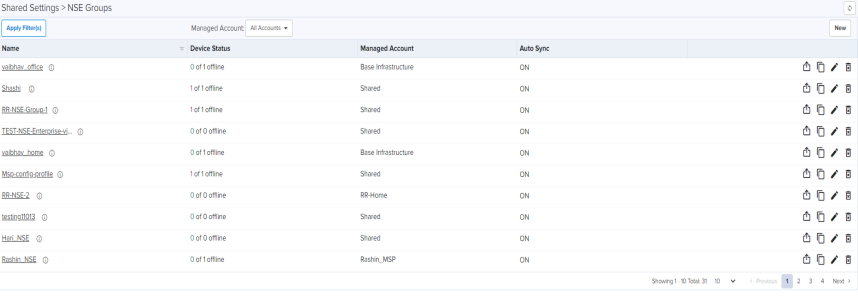
NSE 3000s are configured by creating common configuration profiles called NSE Groups. Configuration associated with an NSE group can be shared by multiple NSEs. Configuration specific to a particular NSE can be set via device overrides (Link to a section on Device Overrides).
To configure the new NSE 3000 configuration, navigate to Configuration > NSE Groups and click New.
Figure 1 NSE Groups
NSE Groups allows you to configure the following:
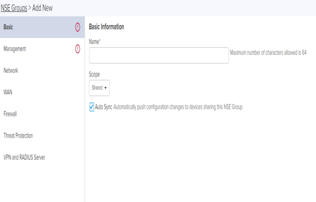
Basic tab allows you to configure the basic profile information like profile name, profile scope, and if the devices using the profile can have their configuration automatically synced.
To edit Basic parameters, perform the following steps:
| 1. | Navigate to Configuration > NSE Groups and click Add New. |
Basic Information tab appears, as shown in Figure 2.
| 2. | Set the values for each parameter, as described in Table 1. |
Table 1: Basic Information parameters
Parameters
Description
Name
Allows to assign the name to the NSE Group.
Scope Allows to select the scope from the drop-down. Auto Sync
Automatically push configuration changes to devices sharing this NSE 3000.
| 3. | Click Save. |
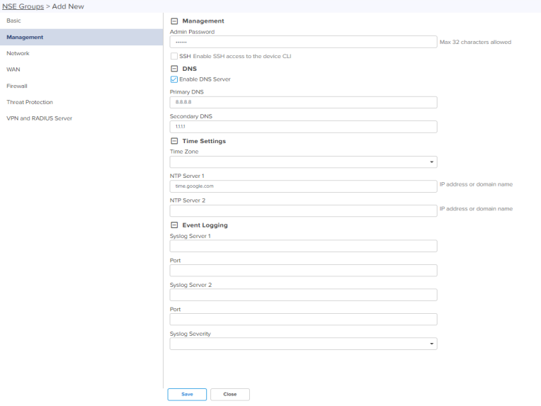
The Management page allows you to set profile parameters such as DNS, Time Settings, and Event logging.
To add or edit Management, perform the following steps:
| 1. | Navigate to Configuration > NSE Groups and click New. |
| 2. | In Add New page, click Management tab. |
Management page appears, as shown in Figure 3.
| 3. | Set the values for each parameter, as described in Table 2. |
Table 2: Management parameters
Parameters
Description
Management
Admin Password
The password used to authentication to the NSE 3000 via SSH/Web.
Enable SSH
Allows to enable SSH access to the device CLI.
DNS
DNS Server
Enable on-box DNS server.
Primary DNS
The IP address of the primary upstream DNS server.
Secondary DNS
The IP address of the secondary upstream DNS server.
Time Settings
Time Zone
The time zone can be set according to the location where the NSE 3000 is installed. Selecting the appropriate time zone from the drop-down, ensures that the device clock is synced with the wall clock time.
NTP Server 1
Name or IPv4 address of a Network Time Protocol server.
NTP Server 2
Name or IPv4 address of a Network Time Protocol server.
Event Logging
Syslog Server 1
The dotted decimal or DNS name of the syslog server address.
Port
The syslog server port (default 514) to which syslog messaging is sent.
Syslog Server 2
The dotted decimal or DNS name of the syslog server address.
Port
The syslog server port (default 514) to which syslog messaging is sent.
Syslog Severity
Provision to configure severity of Logs that must be forwarded to the server. The Log levels supported are as per RFC.
| 4. | Click Save. |
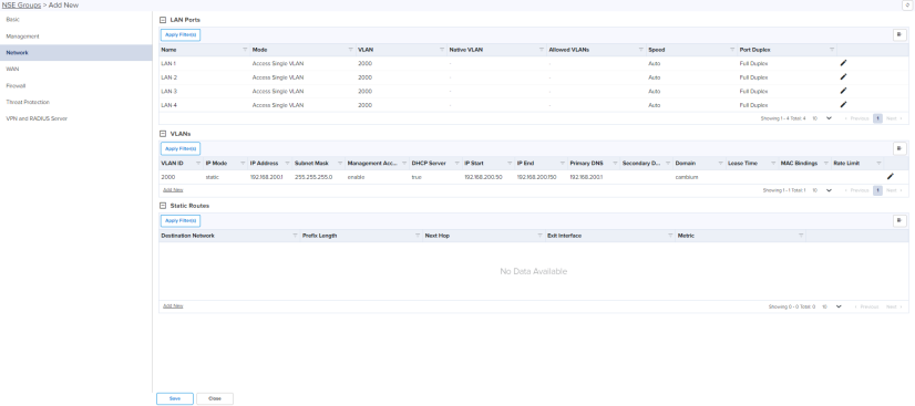
The Network page allows you to configure LAN ports, VLANs, and Static Routes.
To add or edit Network tab, perform the following steps:
| 1. | Navigate to Configuration > NSE Groups and click New. |
| 2. | In Add New page, click Network tab. |
Network page appears, as shown in Figure 4.
| 3. | Set the values for each parameter, as described in Table 3. |
Parameters
Description
LAN Ports
Name Displays the LAN port name. Mode Configure the VLAN mode on the port. The two options are:
Single Access VLAN: The port acts as an access port and all ingress traffic is classified as belonging to the configured VLAN.
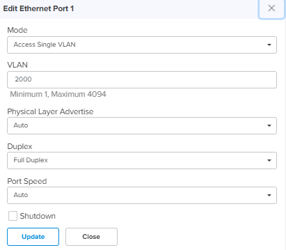
Trunk Multiple VLANs: The port acts a trunk port. VLAN Applicable only when the Mode is set to Single Access VLAN. All ingress traffic is classified as belonging to the configured VLAN. Egress traffic is sent untagged. Native VLAN Applicable only when the Mode is set to Trunk Multiple VLANs. All ingress and untagged traffic on this port is classified as belonging to this VLAN. Tagged Applicable only when the Mode is set to Trunk Multiple VLANs. Enabled tagging of egress traffic belonging to the native VLAN. Allowed VLANs Applicable only when the Mode is set to Trunk Multiple VLANs. Specify a comma separated list of VLANs that are allowed on this port. Speed Configure the port speed. Default is Auto. Advertise Configure the port speed that needs to be advertised. Default is Auto. Port Duplex Configure the port in either Full Duplex or Half Duplex mode. Shutdown Enable or disable the port.. 
Allows to edit the LAN Ports configuration as shown in Figure 5.
Click Update to save the changes.
VLANs
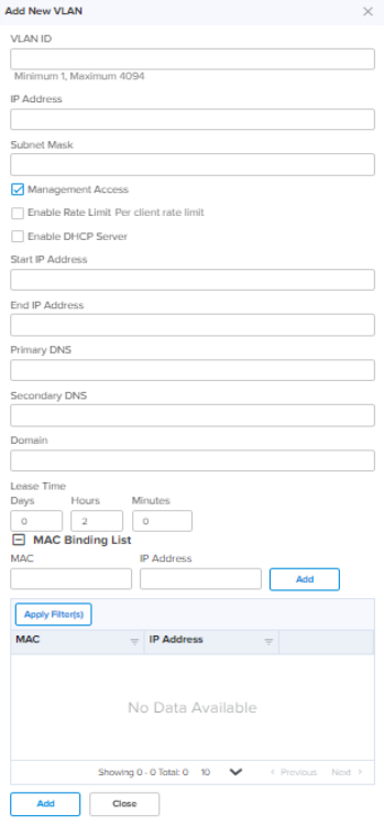
VLAN ID Specify the VLAN ID. IP Address Configure the IP address for the VLAN layer-3 interface. Subnet Mask Configure the subnet mask for the IP address of VLAN layer-3 interface. Management Access Allows to enable or disable the management access via this interface. Enable Rate Limit Allows to enable or disable the Rate Limit Per client rate limit. Rate Limit Specify the rate of requests sent or received. DHCP Server Enable or Disable DHCP server for this VLAN. IP Start Configure the start IP for the DHCP IP Pool. IP End Configure the end IP for the DHCP IP Pool. Primary DNS Configure the primary DNS server for clients on this network. If the DNS server option has been enabled on the NSE, the IP address configured for this VLAN layer-3 interface can be provided as the DNS server for this network. Secondary DNS Configure the secondary DNS server for clients on this network. Domain Configure the DNS search domain for this network. Lease Time Configure the DHCP lease expiry time for this DHCP pool. MAC Bindings For every DHCP configured, the user can bind MAC and IP from the address defined, so that the client gets the same IP address every time they connect. Following parameters are required to bind IP address:
MAC Address
IP Address
Add New Allows to add the new VLANs as shown in Figure 6.
Click Add by entering the parameter.
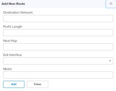
Static Routes Destination Network Specify the destination IP address/network for this route. Prefix Length Specify the prefix length for the destination IP/network for this route. Subnet Mask Specify the subnet mask for the destination IP/network for this route. Next Hop Configure the next hop IP address for this route. Exit Interface Select the exit interface from the drop-down. Metric Configure the metric for this route. Default metric value is 0. Add New Allows to add the new Static Routes as shown in Figure 7.
Click Add by entering the parameter.
| 4. | Click Save. |
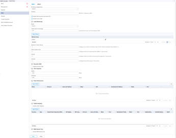
The WAN page allows the user to configure the device’s IP address based on the IP mode.
To add or edit the WAN-1 and WAN-2 tab, perform the following steps:
| 1. | Navigate to Configuration > NSE Groups and click New. |
| 2. | In Add New page click WAN. |
WAN page appears, as shown in Figure 8.
Figure 8 WAN page Dynamic mode
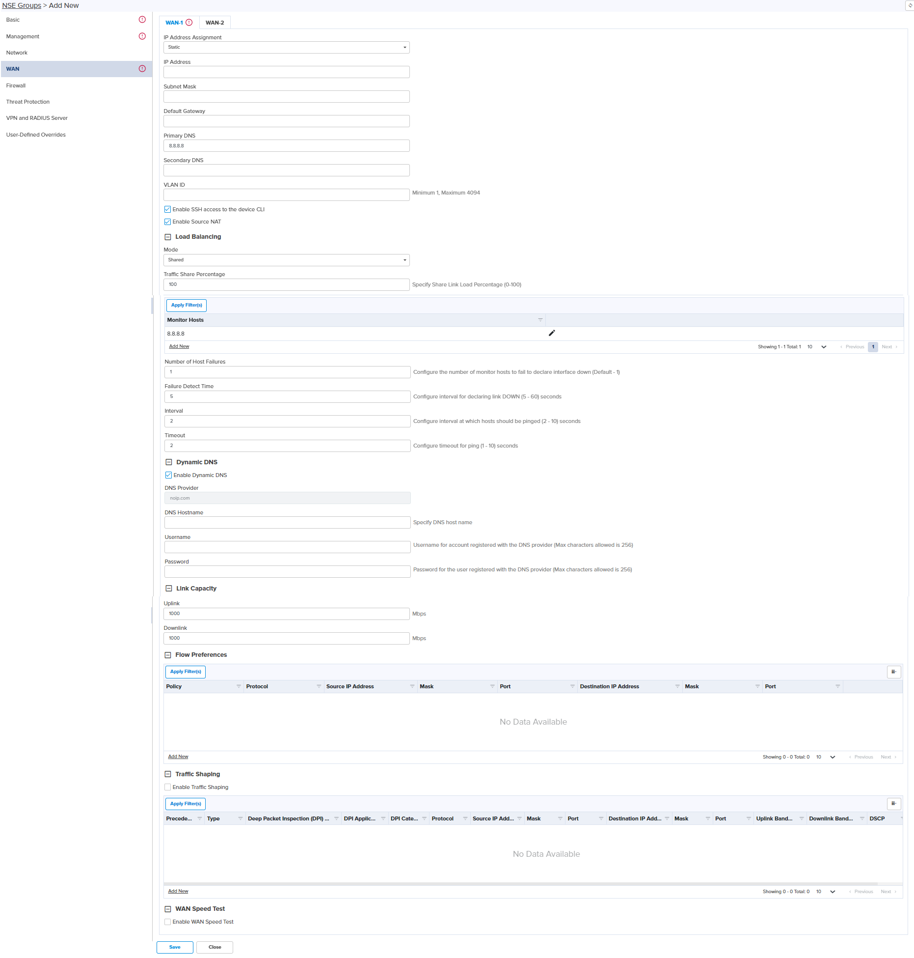
| 3. | Set the values for each parameter, as described in Table 4. |
Parameters
Description
IP Address Assignment Determines the IP Address Assignment of WAN interface such as:
Dynamic
Static
PPPoE VLAN ID
VLANs are identified by a VLAN ID (a number between 1 – 4094). VLAN configuration is optional.
When configured 802.1q header is added to all transmitted frames and received frames are expected to include 802.1q header with the same VLAN ID.
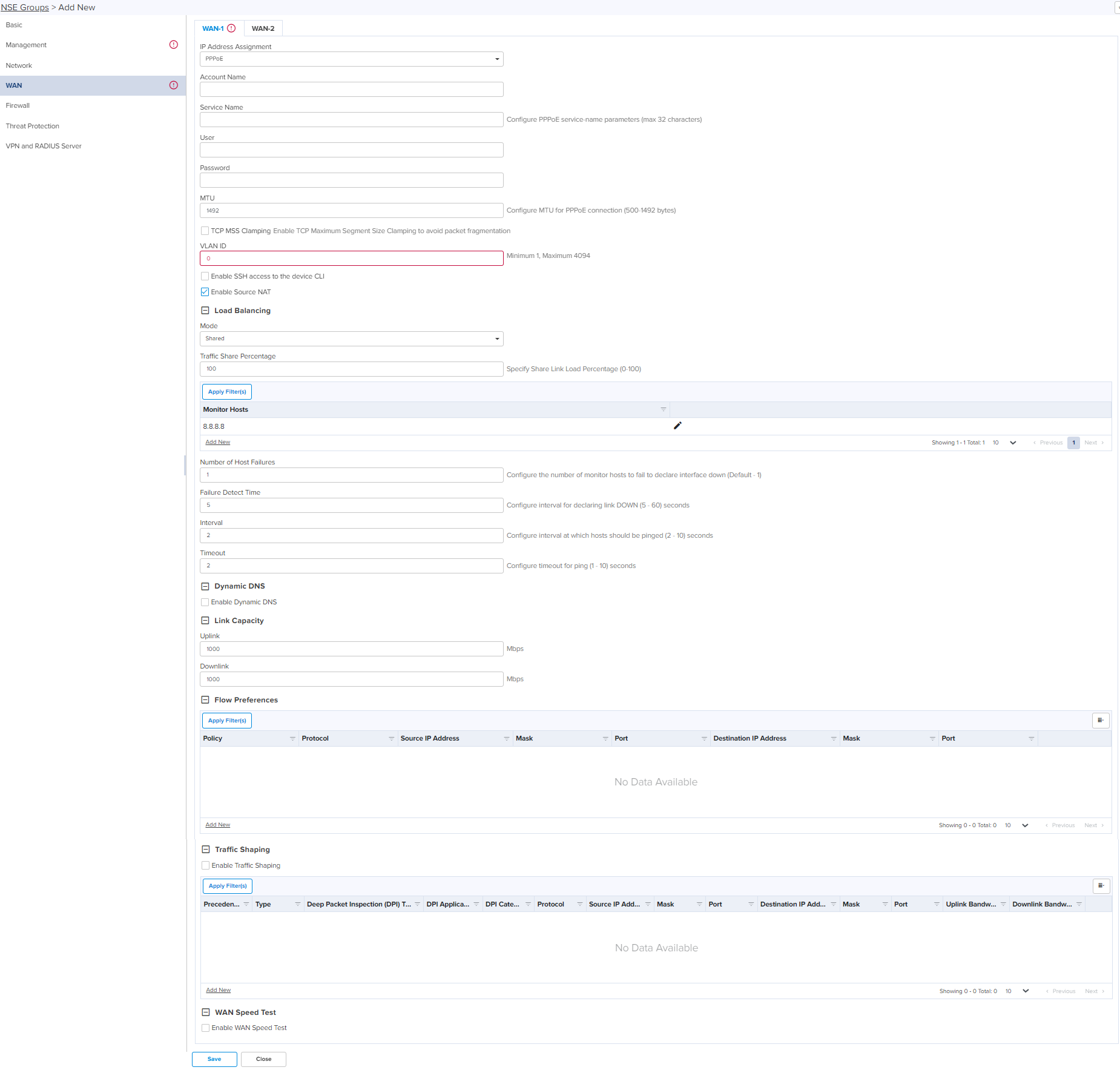
Following parameters appear only when you select the mode as Static in the IP Mode, as shown in Figure 9. IP Address Configure the IP address for the WAN interface. Subnet Mask Configure the subnet mask for the IP address of WAN interface. Default Gateway Configure the default Gateway for the WAN interface. Primary DNS Configure the IP address of primary upstream DNS server on this Interface. Secondary DNS Configure the IP address of secondary upstream DNS server on this interface. Following parameters appear only when you select the mode as PPPoE in the IP Address Assignment, as shown in Figure 10. Account Name
Configure name of the Access Concentrator (max 32 characters). Account Name configuration is optional. Service Name
Configure Service name (max 32 characters). Service name configuration is optional. Service name is used to identify a service with the Access Concentrator. Examples of service name can be a ISP name or a class or quality of service. User Name Configure User Name for PPPoE authentication. User Name configuration is mandatory. Password Configure Password for PPPoE authentication. Password is optional field. MTU Configure MTU for PPPoE Interface. MTU ranges from 500-1492 bytes. Default is 1492 bytes. TCP MSS Clamping Enable or Disable TCP MSS Clamping. Following parameters appear when you select any of the IP Address Assignment modes. Enable SSH Enable or disable SSH access to the device CLI. Enable Source NAT Enable or disable Source NAT on this interface. Load Balancing Mode Determines the load balancing adjust mode of device.
This parameter supports the following modes:
Disabled – This mode disables this WAN link from participating in WAN link load sharing, and failover procedures.
Shared – This mode enables this WAN link to actively forward a percentage of user traffic. The percentage of user traffic on this link is set via the ‘Traffic Share Percentage’ parameter.
Backup – In this mode, the WAN link forwards user traffic only when all of the Shared WAN interfaces are deemed down. Select the required mode.
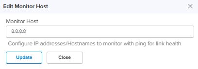
Traffic Share Percentage Specify Share Link Load Percentage (0-100). Monitor Host Configure IP addresses/Hostnames to monitor with ping for link health. Allows to edit the Monitor Host configuration as shown in Figure 11.
Click Update to save the changes.
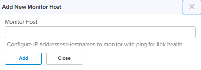
Add New Allows to add the new monitor host as shown in Figure 12.
Click Add by entering the parameters.
Number of Host Failures Configure the number of monitor hosts to fail to declare interface down (Default - 1). Failure Detect Time Configures interval of declaring link DOWN (5 - 60) seconds from the drop-down. Interval Configures interval at which hosts should be pinged (2 - 10) seconds from the drop-down. Timeout Configures timeout for ping (1 - 10) seconds from the drop-down. Dynamic DNS Enable Dynamic DNS Enable or disable Dynamic DNS for this interface. DNS Provider Displays the name of DNS provider.
Example: noip.com
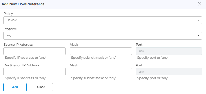
DNS Hostname Specify DNS host name. Username Username of account registered with the DNS provider. Password Password of the user registered with the DNS provider. Link Capacity Uplink Specify the WAN uplink capacity in Mbps. Downlink Specify the WAN downlink capacity in Mbps. Flow Preferences Policy Configure the flow preference policy. There are two options:
Flexible – Allow traffic to failover if the preferred WAN link goes down.
Strict – Traffic is dropped in strict mode, if the preferred WAN link goes down. Protocol Applicable only when the Type is Layer 3. Specify the preferences to which the Layer 3 traffic belongs. There are three options:
TCP – Match TCP preferences.
UDP – Match UDP preferences.
Any – Match any of the above preferences. Source IP Address Specify the IP address for this flow preferences. Mask Specify subnet mask for this flow preferences. Port Specify the source port for this flow preference. Destination IP Address Specify the Destination IP address for this flow preferences. Mask Specify subnet mask for this flow preferences. Port Specify the destination port for this flow preference. Add New Allows to add the new Flow Preferences as shown in Figure 14.
Click Add by entering the parameters.
Traffic Shaping Enable Traffic Shaping Enable or disable the Traffic Shaping. Precedence Specify the precedence for this traffic shaping rule. Type Configure the type of filter rule. There are two options:
Layer 3 – Allows to configure traffic shaping based on IP address and protocol type.
Layer 7 – Allows to configure traffic shaping based on website addresses. Deep Packet Inspection (DPI) Type Applicable only when the Type is Layer 7. There are two options:
Application – Specific type of application within a category.
Category – All applications belonging to a category (eg. Social Messaging). DPI Application Applicable only when the DPI Type is set to Application. Specify the type of Application. DPI Category Applicable only when the DPI Type is set to Category. Specify the Application Category. Protocol Applicable only when the Type is Layer 3. Specify the protocol to which the Layer 3 traffic belongs. There are four options:
TCP – Match TCP traffic.
UDP – Match UDP traffic.
ICMP – Match ICMP traffic.
Any – Match any of the above protocol traffic. Source IP Address Specify the IP address for this shaping rule. Mask Specify subnet mask for this shaping rule. Port Displays the source IP Address port to which IP address messaging is sent. Destination IP Address Specify the Destination IP address for this shaping rule. Mask Specify subnet mask for this shaping rule. Port Displays the source IP Address port to which IP address messaging is sent. Uplink Bandwidth Configures the Uplink Bandwidth from the drop-down. Add New Allows to add the new Traffic Shaping Rule as shown in Figure 13.
Click Add by entering the parameters.
WAN Speed Test Enable or Disable WAN speed test.
Figure 13 New traffic shaping rule
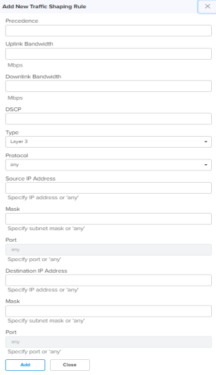
Figure 14 Add new flow preferences
| 4. | Click Save. |
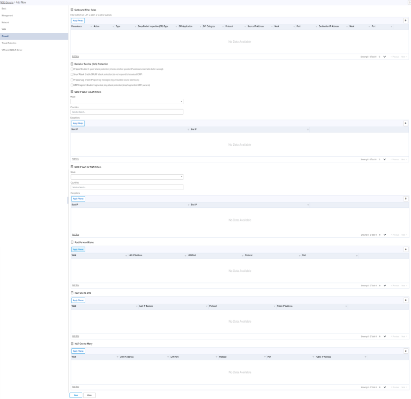
NSE 3000 next-generation firewall allows the user to configure the Layer3 and Layer7 outbound rules, GEO IP filters, Port Forward Rules, One-to-One NAT mappings, and One-to-Many NAT mappings. All inbound connections are denied by default. You can configure port forwarding or NAT rules to allow inbound traffic. Outbound traffic is allowed by default. Using Layer7 outbound rules, users can create rules to block websites without specifying IP addresses or port ranges. Layer7 rules allow the user to block a specific type of application within a category or all applications belonging to a category (eg Social Messaging).
To add or edit the Firewall page, perform the following steps:
| 1. | Navigate to Configuration > NSE Groups and click New. |
| 2. | In Add New page, click Firewall. |
Firewall page appears, as shown in Figure 15.
| 3. | Set the values for each parameter, as described in Table 5. |
Parameters
Description
Outbound Filter Rules Precedence Specify the precedence for this filter rule. Action Determines the action of filter.
This parameter supports the following action:
Permit - Allow traffic matching this filter rule.
Deny - Drop traffic matching this filter rule. Select the required action.
Type Configure the type of filter rule. There are two options:
Layer 3 – Allows to configure filter rule based on IP address and protocol type.
Layer 7 – Allows to configure filter rule based on website addresses. Deep Packet Inspection (DPI) Type Applicable only when the Type is Layer 7. There are two options:
Application – Specific type of application within a category.
Category – All applications belonging to a category (eg. Social Messaging). DPI Application Applicable only when the DPI Type is set to Application. Specify the type of Application. DPI Category Applicable only when the DPI Type is set to Category. Specify the Application Category. Protocol Applicable only when the Type is Layer 3. Specify the protocol to which the Layer 3 traffic belongs. There are four options:
TCP – Match TCP traffic.
UDP – Match UDP traffic.
ICMP – Match ICMP traffic.
Any – Match any of the above protocol traffic. Source IP Address Specify the Source IP address for this filter rule. Mask Specify subnet mask for this filter rule. Port Applicable only when protocol is TCP or UDP. Specify the TCP or UDP port number in the range 1 to 65535. Destination IP Address Specify the Destination IP address for this filter rule. Mask Specify subnet mask for this filter rule. Port Applicable only when the protocol is TCP or UDP. Specify the TCP or UDP port number in the range 1 to 65535. Add New Allows to add the new Filter Rule as shown in Figure 16.
Click Add by entering the parameters.
Denial of Service (DoS) Protection IP Spoof Enable this IP spoof attack protection settings to check whether spoofed IP address is reachable before accept. Smurf Attack Enable this settings for SMURF attack protection (do not respond to broadcast ICMP). IP Spoof Log Enable this settings for IP spoof log messages (log unroutable source addresses). ICMP Fragment Enable this ICMP Fragmnet settings for fragmented ping attack protection (drop fragmented ICMP packets). GEO IP WAN to LAN Filters
GEO IP WAN to LAN filters allows users to configure rules to permit/deny traffic based on the source country of inbound traffic.
Mode Configure GEO IP WAN to LAN Filters Mode. There are three options:
Allow Only (Deny by default) – Allow traffic coming from the countries matching the configured countries. The traffic coming from the countries which are not part of the configured countries will be dropped.
Deny Only (Allow by default) – Block traffic coming from the countries matching the configured countries. The traffic coming from countries that are not part of the configured countries will be allowed
None – Disables the feature. Traffic is allowed from all the countries. Countries Select the required source country of inbound traffic from the drop-down. Exceptions
Exceptions allow users to configure source IP address ranges that are allowed in the inbound traffic.
Start IP Specify the start IP address. End IP Specify the end IP address. Add New Allows to add the new Exceptions as shown in .
Click Add by entering the parameters.
GEO IP LAN to WAN Filters
GEO IP LAN to WAN Filters allows users to configure rules to permit/deny traffic based on the destination country of outbound traffic.
Mode Determines the GEO IP WAN to LAN Filters mode. There are three options:
This parameter supports the following modes:
Allow Only (Deny by default) - Allow traffic destined to the countries matching the configured countries. The traffic destined for the countries which are not part of the configured countries will be dropped.
Deny Only (Allow by default) - Block traffic destined to the countries matching the configured countries. The traffic destined for the countries which are not part of the configured countries will be allowed
None – Disables the feature. Traffic is allowed in all countries. Countries Select the required source country of outbound traffic from the drop-down. Exceptions
Exceptions allow users to configure destination IP address ranges that are allowed in the outbound traffic.
Start IP Specify the start IP address. End IP Specify the end IP address. Add New Allows to add the new Exceptions as shown in .
Click Add by entering the parameters.
Port Forward Rules
Port Forward Rules allow users to forward traffic destined to the WAN Interface IP address of NSE 3000 on a specific TCP or UDP port to any of the LAN IP address. Port Forward Rules provides remote access to internal resources.
WAN Specify the WAN Interface (wan1 or wan2) on which port forwarding is required LAN IP Address Specify the LAN IP address to which traffic will be forwarded. LAN Port Configure the LAN Port to which the forwarded traffic will be sent. Protocol Configure the protocol of forwarded traffic. TCP or UDP.
Port Configure the destination port of the incoming traffic on the WAN interface. Add New Allows to add the new Port Forward Rule as shown in Figure 18.
Click Add by entering the parameters.
NAT One-to-One
NAT One-to-One allows users to map an IP address on the WAN side to a LAN IP address. The IP address on the WAN side should be different from any of the WAN interface (wan1/wan2) IP addresses. NAT One-to-One rules provide remote access to any of the LAN resources.
WAN Specify the WAN interface (wan1 or wan2) on which NAT is required. Public IP Address Specify the Public IP address on the WAN side that is used to access the LAN resource. The public IP address is different from the IP address of the WAN (wan1/wan2) interfaces. LAN IP Address Specify the LAN IP address of the server which is hosting the resource. Protocol Configure the Protocol of the incoming traffic. TCP or UDP.
Add New Allows to add the new NAT One-to-One as shown in Figure 19.
Click Add by entering the parameters.
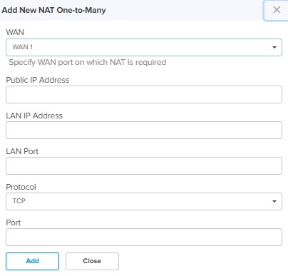
NAT One-to-Many
NAT One-to-Many provides remote access to internal resources. It maps a public IP address to multiple LAN IP’s and ports.
WAN Specify the WAN interface (wan1 or wan2) on which NAT is required. Public IP Address Specify the Public IP address on the WAN side that is used to access the LAN resource. The public IP address is different from the IP address of the WAN (wan1/wan2) interfaces. LAN IP Address Specify the LAN IP address of the server which is hosting the resource. LAN Port Configure the LAN Port which is hosting the resource. Protocol Configure the Protocol of the incoming traffic. TCP or UDP.
Port Configure the destination port of the incoming traffic on the WAN interface. Add New Allows to add the new NAT One-to-Many as shown in Figure 20.
Click Add by entering the parameters.
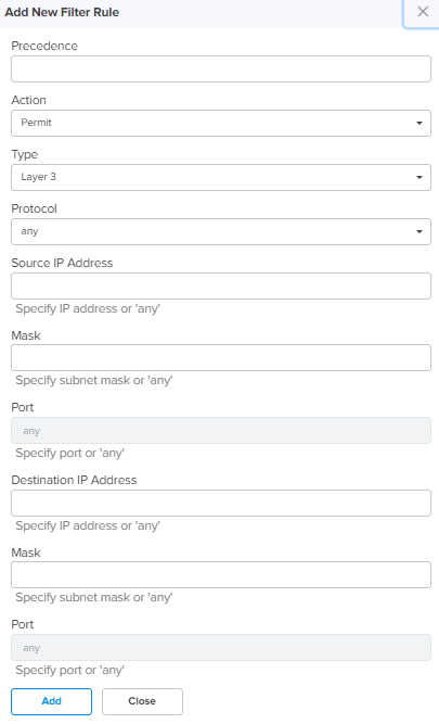
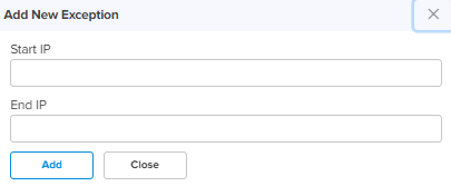
Figure 18 Add new port forward rule
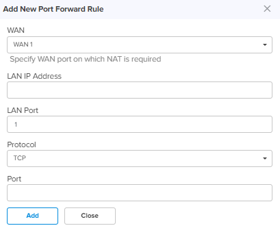
Figure 19 Add new NAT One-to-one
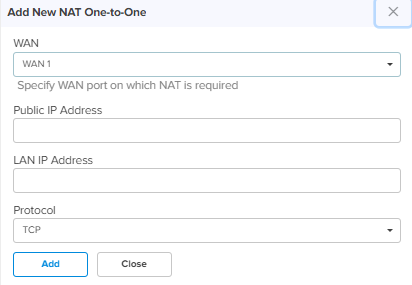
Figure 20 Add new NAT One-to-Many
| 4. | Click Save. |
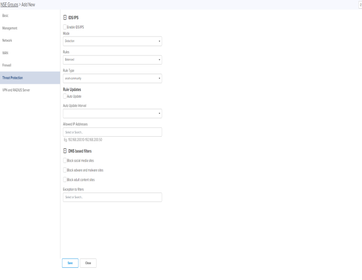
The Threat Protection tab allows the user to configure the DNS based filter and Intrusion Detection and Prevention system (IDS/IPS).
NSE 3000 supports industry leading IDS/IPS engine. IPS engine uses a series of rules that help define a malicious network activity. IPS engine supports rules from Snort and Emerging threats. The solution supports both community and licensed rules. The IPS engine uses these rules to find packets that match against them and generates alerts for users.
NSE 3000 supports DNS based filters. DNS based filters allows users to block certain category of websites. DNS based filters allows to explicitly allow certain list of websites from the blocked list. For example, if user blocks social-media category then all the social websites will be blocked including linked.com since linkedin.com belongs to social-media category. Adding linked.com to Exception to filters list will enable linked.com to fully operational while blocking other social-media websites.
To add or edit the Threat Protection tab, perform the following:
| 1. | Navigate to Configuration > NSE Groups and click New. |
| 2. | In Add New page, click Threat Protection. |
Threat Protection page appears, as shown in Figure 21.
Figure 21 Threat protection page
| 3. | Set the values for each parameter, as described in Table 6. |
Table 6: Threat Protection parameters
Parameters
Description
IDS/IPS Enable IDS/IPS Enable or Disable IDS/IPS. Mode Configure IDS/IPS mode. There are two options:
Detection – IDS/IPS operating in detection mode, detects malicious activity and generates alerts for users.
Prevention – IDS/IPS operating in prevention mode, detects malicious activity, generates alerts for users and takes action to prevent attacks. Rules Configure IDS/IPS rule policy. There are three options:
Connectivity – Policy designed to favor device performance over the security controls in the policy.
Balanced – This policy is the default policy that is recommended for initial deployments. This policy attempts to balance security needs and performance characteristics.
Security – This policy is designed for customer base that is extremely concerned about organizational security. This policy is deployed in networks that have higher security requirements. Rule Type Configure IDS/IPS Rule Type. There are four options:
snort-community – community rule set is a GPLv2 Talos certified ruleset that is distributed free of charge and without any license restrictions. The rules are updated every Tuesday and Thursdays.
snort-vrt – Snort Subscriber Rule Set is developed by Talos research team and is governed by License agreement. Rule Set is updated on Tuesday and Thursdays. Snort-vrt rule set requires an oinkcode to download and activate rules.
emerging-threats open – consists of signatures contributed from the community. et-open rule sets are distributed free of charge.
emerging-threats pro – consists of signatures created as a result of Proofpoint research. The rule sets are governed by License agreement. et-pro rule set requires an oinkcode to download and activate the rules. Rule Updates Auto Update Enable or Disable Auto Update of IDS/IPS Rules. When Auto Update is enabled, NSE 3000 will periodically download the IDS/IPS rules and activates the rules. Update Interval Configure Auto Update Interval for the periodic download of IDS/IPS rules. There are two options:
12 Hours – Update the rules every 12 hours.
24 Hours – Update the rules every 24 hours. Allowed IP Addresses Configure Allowed IP Addresses or Range of Allowed IP Addresses. IDS/IPS operating in prevention mode blocks traffic from a host on detecting malicious traffic from the host. When an IP address is part of Allowed IP Addresses, IDS/IPS will not block traffic from the host even when malicious traffic is detected. DNS based filters Block Social-Media Enable this setting to block traffic to Social-Media category. Block Adware-Malware Enable this setting to block traffic to Adware-Malware category. Block adult content sites Enable this setting to block traffic to Pornography category. Exception to filters Configure specific URL patterns that are to be allowed.
| 4. | Click Save. |
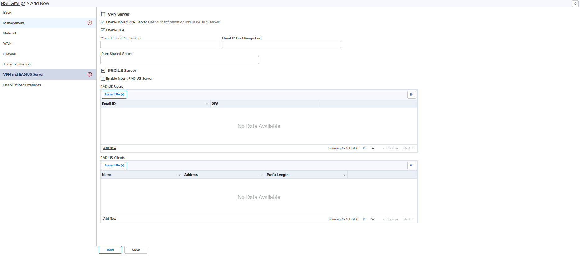
The VPN and Radius Server tab allows the user to configure the VPN Server and Radius Server.
NSE 3000 provides on-board VPN server which allows remote users to establish connection using the native VPN client supported in most of the operating systems. VPN server uses the L2TP/IPsec protocol with the IPSEC encryption and hashing algorithms. VPN server maintains pool of IP addresses. VPN server leases the IP addresses from this pool for remote users.
NSE 3000 provides on-board Radius server which allows authentication and accounting of enterprise and remote users. Radius server lets you maintain user profiles in a central database.
To add or edit the VPN and Radius Server page, perform the following steps:
| 1. | Navigate to Configuration > NSE Groups and click New. |
| 2. | In Add New page, click VPN and Radius Server. |
VPN and Radius Server page appears, as shown in Figure 22.
Figure 22 VPN and Radius server
| 3. | Set the values for each parameter, as described in Table 7. |
Table 7: VPN and Radius server parameters
Parameters
Description
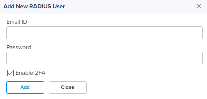
VPN Server Enable inbuilt VPN Server Enable or Disable in-built VPN Server. Enable 2FA Enable or Disable 2FA. Client IP Pool Range Start Configure the start IP for the DHCP IP Pool. Client IP Pool Range End Configure the end IP for the DHCP IP Pool. IPsec Shared Secret Enter a pre shared key string for the IPsec protocol. The shared secret is used between the VPN Client and Server for device authentication. Radius User Enable inbuilt RADIUS Server Enable or Disable in-built RADIUS Server. Email ID Enter the valid Email ID of the user. User is either enterprise user or remote user. Password Enter the valid password for the user. Add New Allows to add the new Add New RADIUS User as shown in Figure 24.
Click Add by entering the parameters.
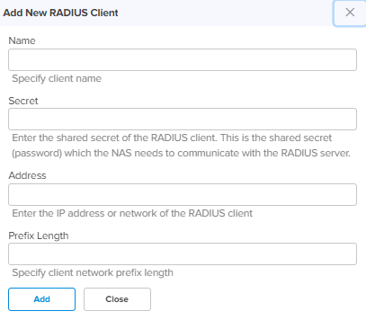
RADIUS Server Name Specify the name for the RADIUS Client. Secret Enter the shared secret of the RADIUS client. This is the shared secret (password) that the NAS needs to communicate with the RADIUS server. Address Enter the IP address or network address of the RADIUS client. Prefix Length Specify client network prefix length. Add New Allows to add the new Add New RADIUS Client as shown in Figure 23.
Click Add by entering the parameters.
Figure 23 Add new RADIUS client
| 4. | Click Save. |
The WAN page allows the user to configure the device’s IP address based on the IP mode.
To view and configure the WAN settings, perform the following steps:
| 1. | From the main NSE 3000 dashboard page, navigate to WAN page. |
The WAN page appears, as shown in Figure 25.
|
|
By default, WAN-1 page is displayed. You can configure WAN on WAN-1 or WAN-2. |

| 2. | Set the values for each parameter, as described in Table 8. |
Table 8: WAN configuration parameters
Parameters
Description
IP Mode
Determines the network that must be configured to use IPv4 addresses.
The following IP modes are supported:
Dynamic
Static
PPPoE
VLAN ID
VLANs are identified by a VLAN ID (a number between 1 – 4094), VLAN configuration is optional. When configured 802.1q header is added to all transmitted frames and received frames are expected to include 802.1q header with the same VLAN ID.
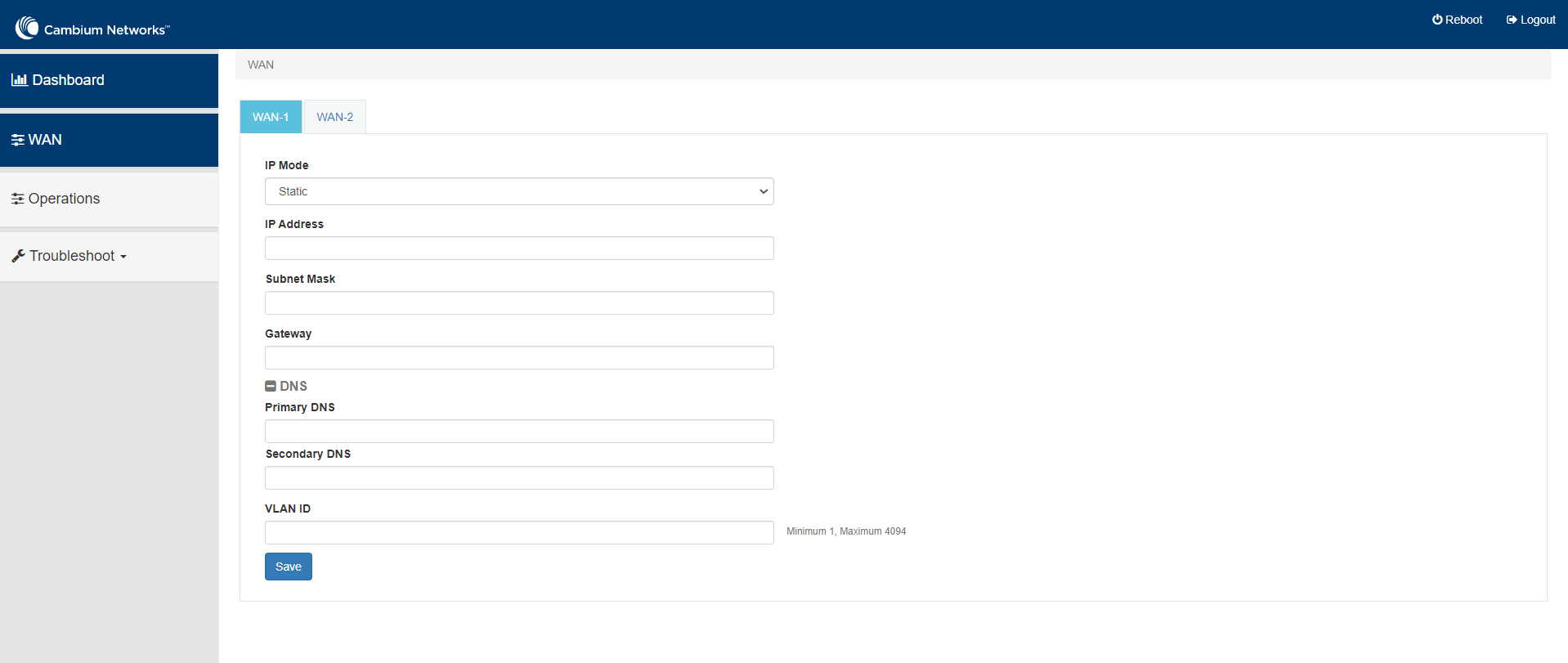
Following parameters appear only when you select the mode as Static in the IP Mode, as shown in Figure 26. IP Address
Specify the 32-bit binary number that identifies a network element by both network and host.
Subnet Mask
Specify the subnet mask for the destination IP/network for this route.
Gateway
Specify the gateway for the destination IP/network for this route.
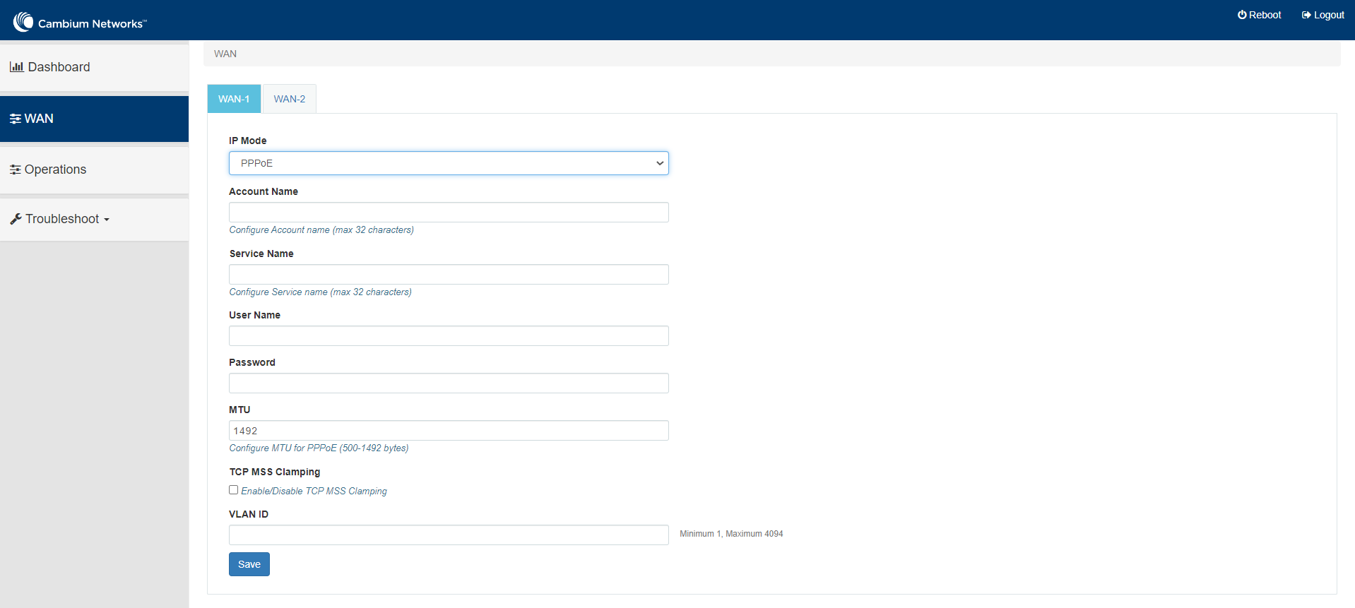
DNS Primary DNS Configure the IP address of primary upstream DNS server on this Interface. Secondary DNS Configure the IP address of secondary upstream DNS server on this Interface. Following parameters appear only when you select the mode as PPPoE in the IP Mode, as shown in Figure 27. Account Name
Configure name of the Access Concentrator (max 32 characters). Account Name configuration is optional. Service Name
Configure Service name (max 32 characters). Service name configuration is optional. Service name is used to identify a service with the Access Concentrator. Examples of Service name can be a ISP name or a class or quality of service User Name Configure User Name for PPPoE authentication. User Name configuration is mandatory. Password Configure password for PPPoE authentication. Password is optional field. MTU Configure MTU for PPPoE Interface. MTU ranges from 500-1492 bytes. Default is 1492 bytes. TCP MSS Clamping Enable or Disable TCP MSS Clamping.
| 3. | Click Save. |