Managing NSE 3000 using cnMaestro
NSE 3000 is managed using the cloud-hosted cnMaestro (a management solution from Cambium Networks).
This section covers the following topics:
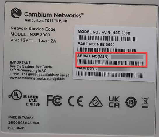
A device manufacturer serial number (MSN) is required to claim an NSE 3000 device. You can find the device MSN at the bottom of the device as shown in Figure 1.
Figure 1 MSN of the NSE 3000 device
To claim an NSE 3000 device that is associated with a site, complete the following steps:
From the home page, navigate to Monitor and Manage.
The System page appears, as shown in Figure 2.
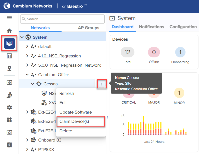
On the left panel, in the Networks section, expand the site panel.
Click theactions (![]() ) icon and select Claim Device(s).
) icon and select Claim Device(s).
The Claim Enterprise Devices window appears, as shown in Figure 3.
Figure 3 The Claim Enterprise Devices window
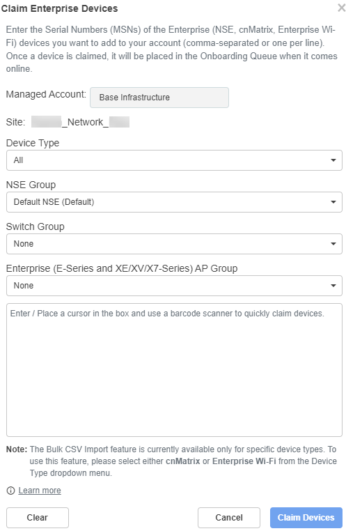
From the NSE Group dropdown list, select the required group.
|
|
Note The selected NSE group is automatically pushed to the device while onboarding. |
In the Enter field, enter the MSN of the NSE 3000 device.
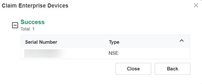
Click Claim Devices.
The NSE 3000 device that is associated with a site is claimed successfully.
The high availability (HA) support allows two NSE 3000 devices to share health information when connected through a LAN port (Port-6). When the devices are connected as an HA pair, one is configured as Primary and the other as Spare. The Spare device serves as a backup in case of hardware failures.
If the Primary device goes down, the Spare device becomes active. When the Primary device is restored, it regains its active state and the Spare device reverts to a backup state.
|
|
Note The HA support is available from NSE release version 1.7 and higher. |
An NSE 3000 device requires a Tier-30 license to onboard to cnMaestro.
An HA pair (Primary - Spare) requires only one Tier-30 license. The Spare device does not require an additional license as it inherits the license from the Primary device.
On the expiry of the license, the device management is deactivated using cnMaestro. However, the devices are not deleted from the device list in cnMaestro.
The following are the constraints on NSE 3000 devices in cnMaestro:
A site can have either a single NSE 3000 device or a single NSE 3000 HA pair.
An HA pair can only be created under a site. NSE group is mandatory for all NSE 3000 devices to onboard to the cnMaestro cloud 5.1.1 version.
An NSE 3000 device must exist (with an NSE group attached) under the site to form an HA pair.
If a device is in the Onboarding state under a site, you cannot claim another device under the same site.
You can create an HA pair using either of the following options:
Onboard as HA spare (from the Onboarding queue)
Claim Device(s) (at the site level)
The HA pair configuration involves the following tasks:
The primary device onboards as a standalone device to cnMaestro. An additional NSE 3000 device can be brought into the onboarding queue (without Tier-30 license) either by bulk claim (on the Onboard page) or using cambium-id and password. An HA pair is formed using the Onboard as HA spare option from the Approve Device window.
|
|
Note
|
When onboarding an NSE 3000 device as a spare, the device automatically inherits the NSE group of the primary device. This holds good even if the devices are claimed at the site level. Additionally, any change in the NSE group of the primary device is automatically reflected in the spare device.
To onboard an NSE 3000 device as a spare device, complete the following steps:
From the home page, click the Onboard (![]() ) icon.
) icon.
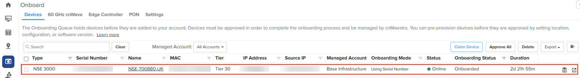
The Onboard page appears.
Figure 4 The Onboard page
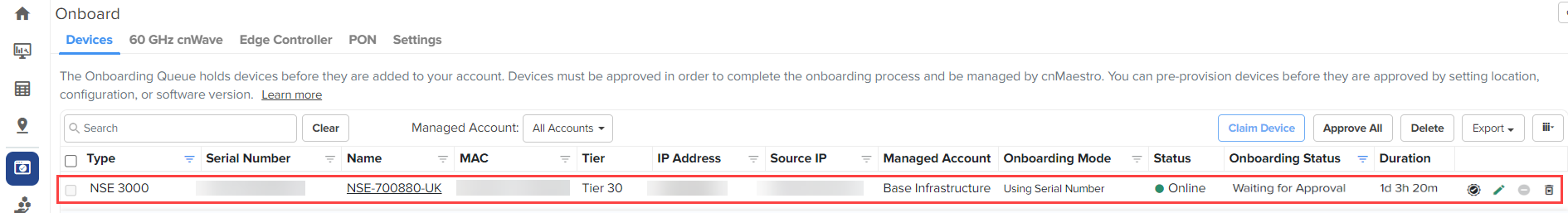
Click the approve device (![]() ) icon of the NSE 3000 device.
) icon of the NSE 3000 device.
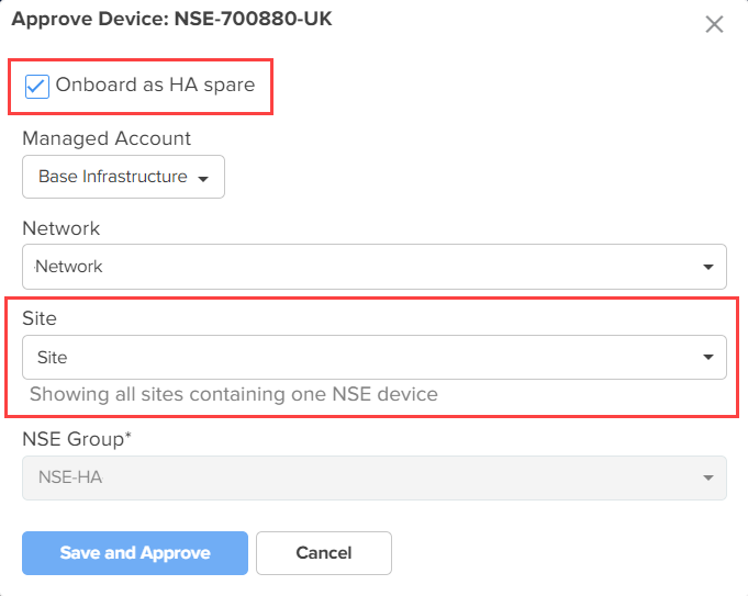
The Approve Device window appears with the Onboard as HA spare option and shows all sites that have only one NSE device (as shown in Figure 5).
Figure 5 The Approve Device window
|
|
Note The spare device has the same NSE group as that of the primary device. |
Click Save and Approve from the Approve Device window (as shown in Figure 5).
The spare device is onboarded (as shown in Figure 6) without an additional Tier-30 license.
Figure 6 Spare device onboarded
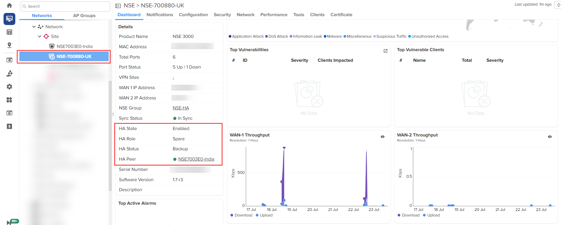
Click on the spare device name.
You can see the spare device under a site (as shown in Figure 7). You can view the HA details in the Details section of the dashboard (as shown in Figure 7).
Figure 7 Details about HA for the Spare device
|
|
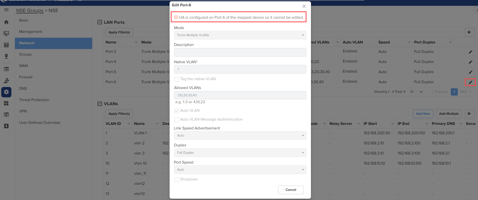
Note When HA is configured on Port-6 of the mapped device, you cannot edit the Port-6 configuration. A message is displayed on the Edit Port-6 window (as shown in Figure 8). |
Figure 8 The Edit Port-6 window
|
|
Note The fields in the Approve Device window (as shown in Figure 5) can also be configured using the Edit Device ( |
An NSE 3000 HA pair can be additionally formed using the Claim Device(s) option at the site level. When a second NSE 3000 device is claimed (assuming the primary already exists under the site), you have the option to claim it as a spare. However, claiming a second NSE 3000 device under the same site as a regular device is restricted.
To claim an NSE 3000 device as an HA spare, complete the following steps:
From the home page, click the Monitor and Manage (![]() ) icon.
) icon.
The System page appears.
On the left panel, in the Networks section, expand the site panel.
Click the actions (![]() ) icon and select Claim Device(s).
) icon and select Claim Device(s).
The Claim Enterprise Devices window appears.
In the Enter field, enter the MSN of the NSE 3000 device.
|
|
Note You can find the device MSN at the bottom of the NSE 3000 device. |
Click Claim Devices.
The Claim Enterprise Devices window appears.
Figure 9 The Claim Enterprise Devices window

Click Yes.
The Claim Enterprise Devices window appears.
Figure 10 The Claim Enterprise Devices window
Click Close.
The device is claimed as an HA spare.
Figure 11 Device claimed as an HA spare
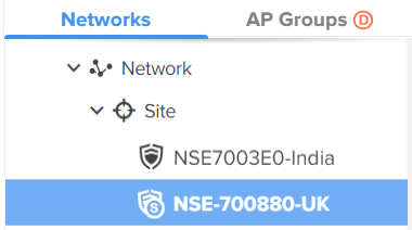
The ( ) icon indicates the primary NSE 3000 device. The (
 ) icon indicates the spare NSE 3000 device.
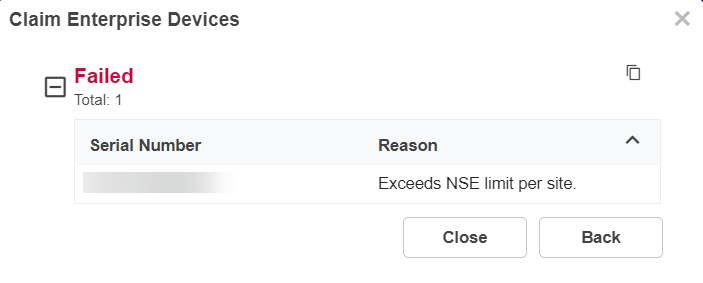
When you click No in the Claim Enterprise Devices window (as shown in Figure 9), the Claim Enterprise Devices window appears (as shown in Figure 12). You cannot claim the device as an HA spare.
Figure 12 The Claim Enterprise Devices window
The NSE 3000 HA pair can be moved as a single unit only. This can be done by changing the Network and Site for the primary device. The devices in the pair cannot be moved individually. Moreover, the NSE 3000 device or HA pair can only be moved to a site that has no NSE 3000 devices. Moving to a network is not allowed.
|
|
Note An HA pair of NSE 3000 devices shares the same NSE group. Consequently, the NSE group selection for the spare device is disabled. |
If one of the NSE 3000 devices in a pair is deleted, the other NSE 3000 device becomes standalone.
When the primary device is deleted from the pair, the spare device becomes a standalone device and the pair's Tier-30 license is mapped to the spare device (instead of the primary device). Also, a configuration job for this standalone device with HA mode Disable is triggered.
When the spare device is deleted from the pair, the primary device becomes a standalone device.
When both primary and spare devices are deleted, a slot is released.
The device overrides are removed from the Onboard page. The bulk overrides cannot be done for NSE 3000 devices.
When HA is enabled in the NSE group, the device overrides in the device context are hidden.
Figure 13 Device overrides are not applied when HA is enabled
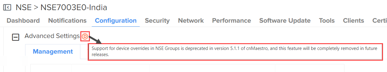
When HA is disabled in the NSE group, the deprecated icon (![]() ) is shown. Device overrides are being deprecated for NSE devices in the 5.1.1 version. When you hover the cursor over the deprecated (
) is shown. Device overrides are being deprecated for NSE devices in the 5.1.1 version. When you hover the cursor over the deprecated (![]() ) icon, a message about the deprecation is displayed (as shown in Figure 14).
) icon, a message about the deprecation is displayed (as shown in Figure 14).
Figure 14 A deprecation message
When you upgrade the firmware on the primary device, the firmware on the spare device is automatically upgraded. This ensures that both primary and spare devices run the same version.
|
|
Note The Software Update tab is available only for the primary device. |
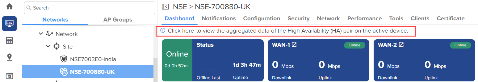
In an HA pair, the active NSE 3000 device shows the aggregated data for the pair. In the spare NSE 3000 device, a banner provides a link to the active device's page (as shown in Figure 15) to view the aggregated data. The same banner is displayed under the Security > Threats, Security > Vulnerabilities, and Clients > Local tabs.
|
|
Note
|
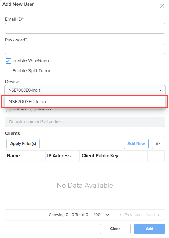
When adding Wireguard clients from the VPN page, only the primary device is listed in the Device dropdown list (as shown in Figure 16).
Figure 16 The Add New User window -Wireguard
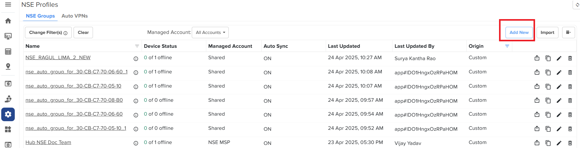
To configure NSE 3000 devices, create configuration profiles called NSE Groups. To create and configure a new NSE 3000 group, navigate to Configuration > NSE Profiles. Select the NSE Groups tab and click Add New.
Figure 17 Creating NSE groups
For a new NSE group, you must configure parameters using the following tabs:
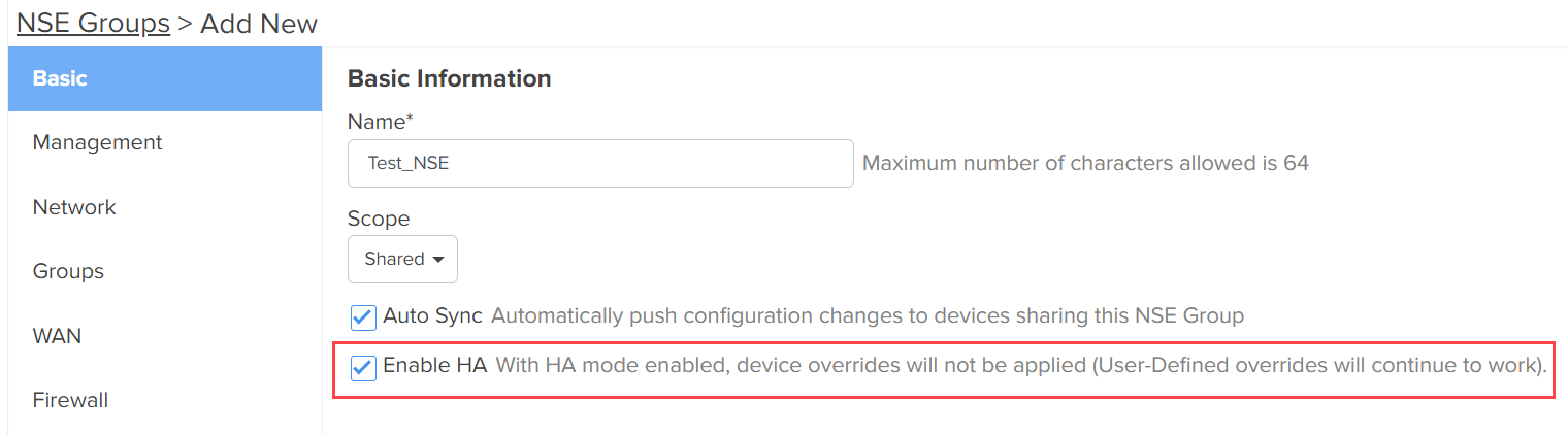
Using the Basic tab, you can configure basic group information, such as group name and group scope. You have the option to enable automatic synchronization of the configuration changes for devices associated with the NSE group.
To configure parameters on the Basic Information page, complete the following steps:
Navigate to Configuration > NSE Groups and click Add New
The Basic Information page appears, as shown in Figure 18.
Figure 18 The Basic Information page
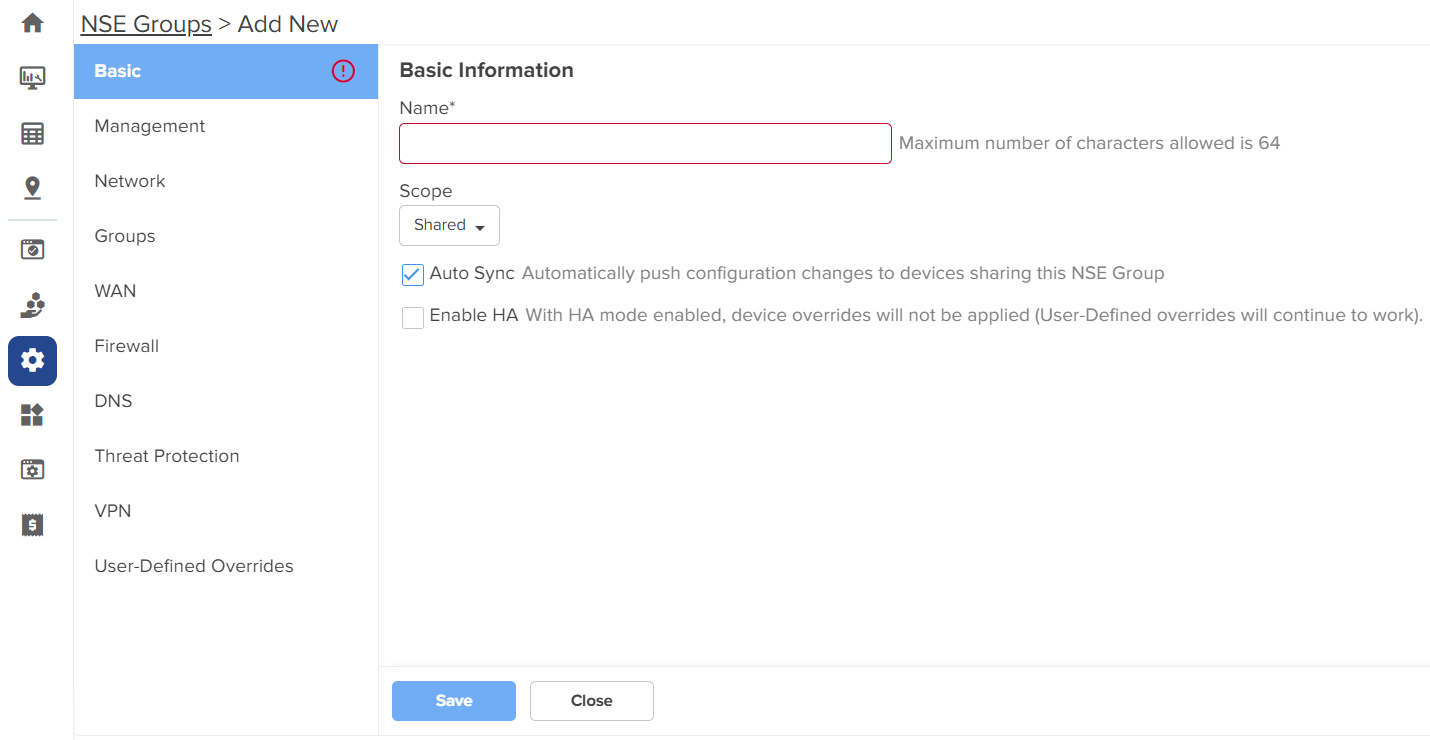
Configure the parameters, as described in Table 1.
Table 1 Parameters on the Basic Information page
|
Parameter |
Description |
|---|---|
|
Name |
Name for the NSE group. This parameter allows a maximum of 64 characters. This is a mandatory parameter. |
|
Scope |
Scope determines the availability of the NSE group across different tenant accounts. By default, the following options are supported:
|
|
Auto Sync |
Specifies whether the configuration changes made to the NSE group are automatically applied to all devices associated with the group. By default, auto sync is enabled. |
|
Enable HA |
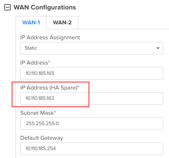
Enables or disables the HA. By default, this parameter is disabled. Note: When this parameter is enabled, you must configure the IP Address (HA Spare) parameter by selecting the Static option from the IP Address Assignment dropdown list in the WAN Configurations section of the WAN screen (as shown in Figure 19). |
Figure 19 The WAN Configurations section
Click Save.
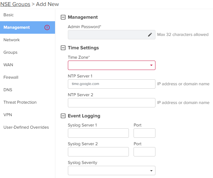
Using the Management tab, you can configure the profile-related parameters such as time settings and event logging.
To configure parameters on the Management page, complete the following steps:
On the NSE Groups > Add New page, select the Management tab.
The Management page appears, as shown in Figure 20.
Configure the parameters, as described in Table 2.
Table 2 Parameters on the Management page
|
Parameter |
Description |
|---|---|
|
On the Management page, there are Management, Time Settings, and Event Logging sections. |
|
|
Management |
|
|
Admin Password |
The password used to authenticate the NSE 3000 users who access through SSH or web. This parameter allows a maximum of 32 characters. This is a mandatory parameter. Note: Click the edit |
|
Time Settings |
|
|
Time Zone |
The time zone based on the installation location of the device. Select an appropriate time zone from the dropdown list to ensure that the device clock is synchronized with the wall clock time. |
|
NTP Server 1 |
The IPv4 address or domain name of the primary Network Time Protocol (NTP) server. |
|
NTP Server 2 |
The IPv4 address or domain name of the secondary or a backup NTP server. |
|
Event Logging |
|
|
Syslog Server 1 |
The IPv4 address or the domain name of the syslog server 1. |
|
Port |
The port number of the syslog server 1 to which the syslog messages are sent. Supported value: 1 to 65535. |
|
Syslog Server 2 |
The IPv4 address or the domain name of the syslog server 2. |
|
Port |
The port number of the syslog server 2 to which the syslog messages are sent. Supported value: 1 to 65535. |
|
Syslog Severity |
The logs with the selected severity level that must be forwarded to the server. The following options are supported:
|
Click Save.
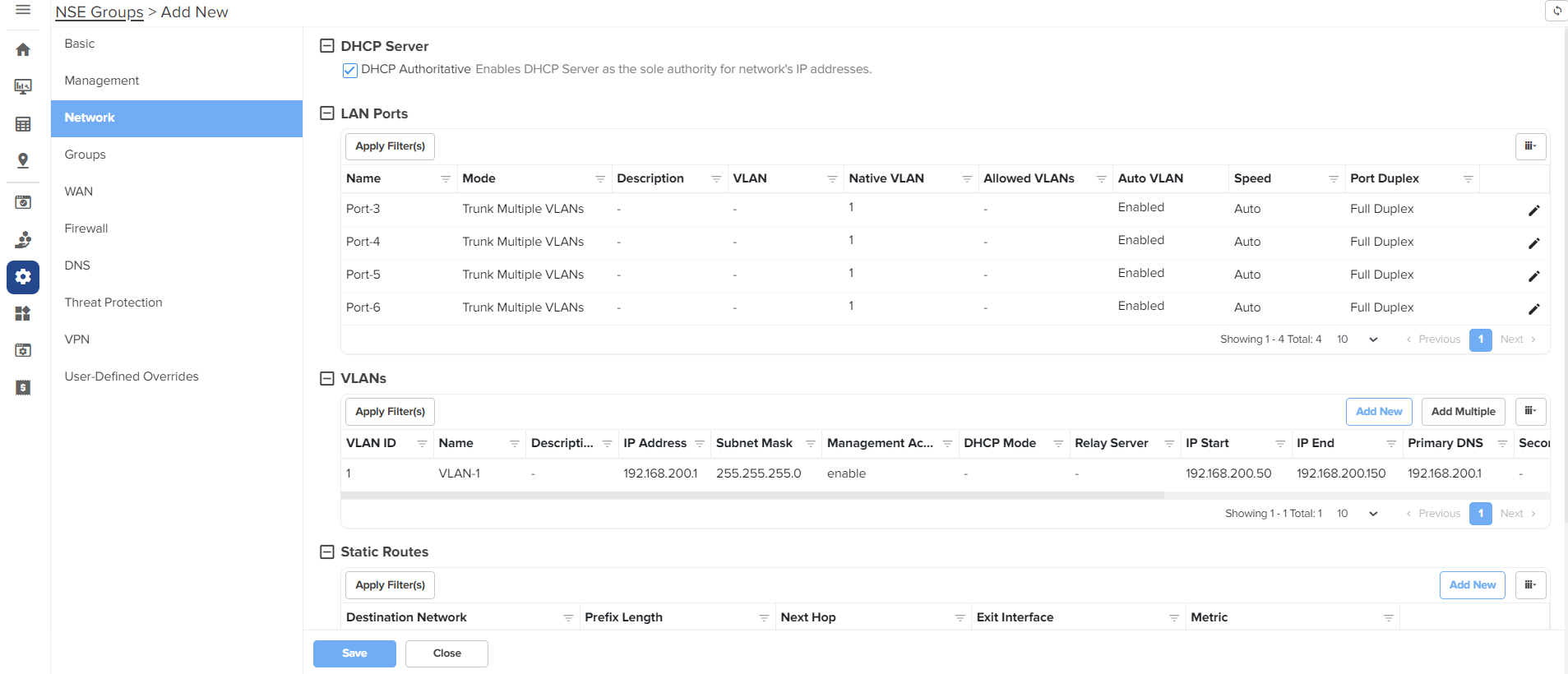
Using the Network tab, you can configure LAN ports, VLANs, and static routes.
To configure parameters on the Network page, complete the following steps:
On the NSE Groups > Add New page, select the Network tab.
The Network page appears, as shown in Figure 21.
Configure the parameters, as described in Table 3.
Table 3 Parameters on the Network page
|
Parameter |
Description |
||
|---|---|---|---|
|
On the Network page, there are DHCP Server, LAN Ports, VLANs, and Static Routes sections. |
|||
|
DHCP Server |
|||
| DHCP Authoritative |
Indicates that the DHCP server is the primary and trusted source for IP address assignments in the network. This parameter is enabled by default. |
||
|
LAN Ports Click the edit |
|||
|
Name |
Name of the LAN port. This parameter cannot be modified. |
||
|
Mode |
The VLAN mode of the port. The following options are supported:
|
||
|
Description |
A brief description of the LAN port. |
||
|
VLAN |
This parameter is applicable only when the Mode parameter is set to Access Single VLAN. By default, VLAN value is 1. VLAN value can be in the range: 1 to 4094 This is a mandatory parameter. |
||
|
Native VLAN |
Indicates that the traffic on the native VLAN is untagged. This parameter is applicable only when the Mode parameter is set to Trunk Multiple VLANs. The Native VLAN value can be in the range: 1 to 4094 This is a mandatory parameter. |
||
|
Tag the native VLAN |
This parameter is applicable only when the Mode parameter is set to Trunk Multiple VLANs. When the Tag the native VLAN parameter is enabled, the native VLAN traffic is tagged with 802.1Q. |
||
|
Allowed VLANs |
This parameter is applicable only when the Mode parameter is set to Trunk Multiple VLANs. This parameter supports a range or comma-separated list of VLANs. Example: 1-3 or 4, 10, 22 |
||
|
Auto VLAN |
This parameter is applicable only when the Mode parameter is set to Trunk Multiple VLANs. This parameter facilitates automatic assignment of VLANs in cnMatrix switches and access points (APs). When this parameter is enabled, the cnMatrix switches and APs use the Link Layer Discovery Protocol (LLDP) packets to obtain a list of VLANs for automatic assignment. Note: Auto VLAN works only with cnMatrix switches and access points (APs). It does not work with any third-party switches and APs. Auto VLAN allows cnMatrix switch to dynamically learn VLANs from an AP. The AP advertises the configured VLANs to the cnMatrix switch. The cnMatrix switch then advertises those VLANs to the uplink NSE 3000 device. This process ensures that VLANs are properly bridged. This parameter is enabled by default. |
||
|
Auto VLAN Message Authentication |
This parameter is applicable only when the Mode parameter is set to Trunk Multiple VLANs. This parameter enables authentication for the LLDP messages where the VLANs are advertised. This parameter is enabled by default. |
||
|
Link Speed Advertisement |
Indicates the port speed that must be configured for advertisement. Default: Auto The following options are supported:
|
||
|
Port Duplex |
Specifies the mode of port communication. The following options are supported:
|
||
|
Port Speed |
Specifies the port speed. Default: Auto The following options are supported:
|
||
|
Shutdown |
Enables or disables the port. By default, this parameter is disabled. |
||
|
VLANs Note: You can configure up to 128 VLANs. To add a new VLAN, click Add New. The Add New VLAN window appears, as shown in Figure 23. To edit an existing VLAN configuration, click the edit |
|||
|
VLAN ID |
Indicates the VLAN ID. The VLAN ID value can be in the range: 1 to 4094 This is a mandatory parameter. |
||
| Name |
Name of the new VLAN. This is a mandatory parameter. |
||
|
Description |
Displays the user-configured description for the VLAN. |
||
|
IP Address |
IPv4 address that is assigned to the VLAN. This is a mandatory parameter. |
||
|
Subnet Mask |
Subnet mask that is assigned to the VLAN. This is a mandatory parameter. |
||
|
Management Access |
Indicates whether the management access is enabled or disabled. By default, this parameter is enabled. |
||
|
Enable Rate Limit |
Indicates whether the rate limit is enabled or disabled. By default, this parameter is disabled. When you select the Enable Rate Limit checkbox, the Rate Limit parameter appears. |
||
|
Rate Limit |
Specifies the rate of requests sent or received. This parameter appears only when you enable the Enable Rate Limit parameter. This parameter supports only integer values. This is a mandatory parameter. |
||
| Enable Port Scan |
A scan identifies open ports within a network and helps in detecting potential vulnerabilities that can be exploited by attackers. By default, this parameter is enabled. |
||
|
Enable Device Identification |
Enables device information (such as MAC, Manufacturer, Type, Model, and OS) of clients connected to NSE devices to be displayed in the NSE Clients page.
|
||
|
DHCP mode |
Specifies the DHCP mode. The following options are supported:
|
||
|
DHCP Server In addition to the below parameters, you must also configure the parameters in the DHCP Options and MAC Binding List sections, as shown in Figure 24. |
|||
|
Start IP address |
Starting IPv4 address in the range. This is a mandatory parameter. |
||
|
End IP address |
Ending IPv4 address in the range. This is a mandatory parameter. |
||
|
Primary DNS |
The primary DNS server for clients on the network. If the DNS server option is enabled on the NSE, the IPv4 address configured for the VLAN can be provided as the DNS server for the network. |
||
|
Secondary DNS |
The secondary DNS server for clients on the network. |
||
|
Domain |
The DNS search domain for the network. |
||
|
Lease Time |
The DHCP lease expiry time for the DHCP pool (in days, hours, and minutes). This is a mandatory parameter. |
||
|
DHCP Options NSE allows configuration of standard and custom DHCP options. To add a new DHCP option, click Add New. The Add New DHCP Option window appears, as shown in Figure 25. To edit an existing DHCP option, click the edit |
|||
|
Option |
The following DHCP options are supported:
This is a mandatory parameter. |
||
|
Code |
A value for the code. This parameter allows a maximum value of 254. This is a mandatory parameter. |
||
|
Type |
The following options are supported:
This is a mandatory parameter. |
||
|
Value |
A value in ASCII. This is a mandatory parameter. |
||
|
MAC Binding List For every DHCP pool configured, the user can bind the client MAC address with an IPv4 address from the network. This enables the client to obtain the same IPv4 address whenever they connect to the NSE 3000 device. Following parameters are required to create the binding list:
When you set MAC and IP address fields and click Add, the binding of MAC and IP address is added. Note: Upto 200 MAC to IP address bindings are supported per DHCP pool. Note: When you bind, the binding IP address should be outside the DHCP pool range. To add a new MAC binding, click Add New. The Add New MAC Binding window appears, as shown in Figure 26. To edit an existing MAC binding, click the edit |
|||
|
MAC |
The MAC address of the client. This is a mandatory parameter. |
||
|
IP Address |
The IPv4 address that must be assigned to the client. This is a mandatory parameter. |
||
|
Description |
Displays the user-configured description. |
||
|
Import |
Imports the MAC bindings. Note: The CSV file that you import must be in the three-column format, for example, MAC, IP address, and Description. To import MAC bindings, click Import. The Import MAC Bindings window appears, as shown in Figure 27. |
||
|
Replace existing list |
Indicates whether the imported bindings will overwrite the existing list or append to the list.
By default, this parameter is enabled. |
||
|
Export |
Exports the configured bindings list. The following options are supported:
To export MAC bindings, click Export. The export options appear, as shown in Figure 28. |
||
|
DHCP Relay |
Indicates whether the DHCP relay unicasts the DHCP request to an external DHCP server. This is a mandatory parameter. |
||
|
Relay Server IP address |
IPv4 address of the external DHCP server. This is a mandatory parameter. |
||
|
Static Routes To add a new route, click Add New. The Add New Route window appears, as shown in Figure 29. To edit an existing route, click the edit |
|||
|
Destination Network |
The IPv4 address of the destination network. This is a mandatory parameter. |
||
|
Prefix Length |
The prefix length for the network address. This parameter supports integer values and a maximum value of 32. This is a mandatory parameter. |
||
|
Next Hop |
The next hop IPv4 address for the route. This is a mandatory parameter. |
||
|
Exit Interface |
The exit interface through which the next hop is reachable. This is a mandatory parameter. |
||
|
Metric |
The metric for the route. |
||
|
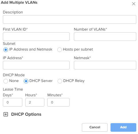
To add multiple VLANs, click the Add Multiple button. The Add Multiple VLANs window appears, as shown in Figure 30. To edit an existing VLAN configuration, click the edit |
|||
|
Description |
Displays the user-configured description for the VLAN. |
||
|
First VLAN ID |
Indicates the first VLAN ID. The supported VLAN ID value range is between 1 and 4094. This is a mandatory parameter. |
||
|
Number of VLANs |
Indicates the number of VLANs that you want to add. Note: You can configure up to 128 VLANs. This is a mandatory parameter. |
||
|
Subnet The following options are supported:
|
|||
|
IP address |
The IPv4 address of the first VLAN. This is a mandatory parameter. |
||
|
Netmask |
The netmask of the subnet. This is a mandatory parameter. |
||
|
First IP Address |
The first IPv4 address of the subnet. This is a mandatory parameter. |
||
|
Hosts per subnet |
The number of hosts that you want for the subnet. This is a mandatory parameter. |
||
|
DHCP mode |
Specifies the DHCP mode. The following options are supported:
|
||
|
Lease Time |
The DHCP lease expiry time for the DHCP pool (in days, hours, and minutes). This is a mandatory parameter. |
||
|
DHCP Options NSE allows configuration of standard and custom DHCP options. To add a new DHCP option, click Add New. The Add New DHCP Option window appears, as shown in Figure 25. To edit an existing DHCP option, click the edit |
|||
|
Option |
The following DHCP options are supported:
This is a mandatory parameter. |
||
|
Code |
A value for the code. This parameter allows a maximum value of 254. This is a mandatory parameter. |
||
|
Type |
The following options are supported:
This is a mandatory parameter. |
||
|
Value |
A value in ASCII. This is a mandatory parameter. |
||
|
DHCP Relay |
Indicates whether the DHCP relay unicasts the DHCP request to an external DHCP server. This is a mandatory parameter. |
||
|
Relay Server IP address |
IPv4 address of the external DHCP server. This is a mandatory parameter. |
||
Figure 22 The Edit Port window
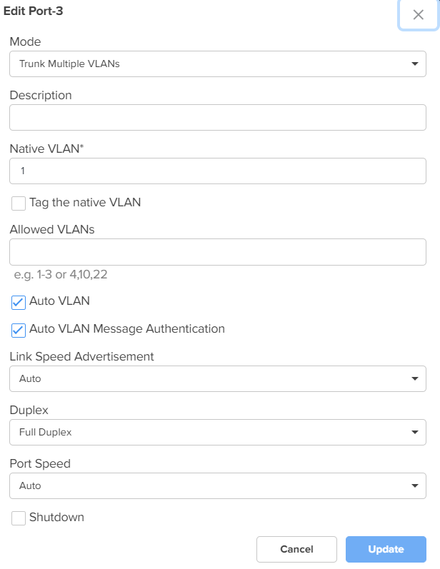
Figure 23 The Add New VLAN window
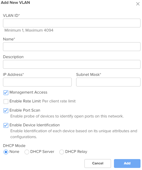
Figure 24 DHCP Options and MAC Binding List
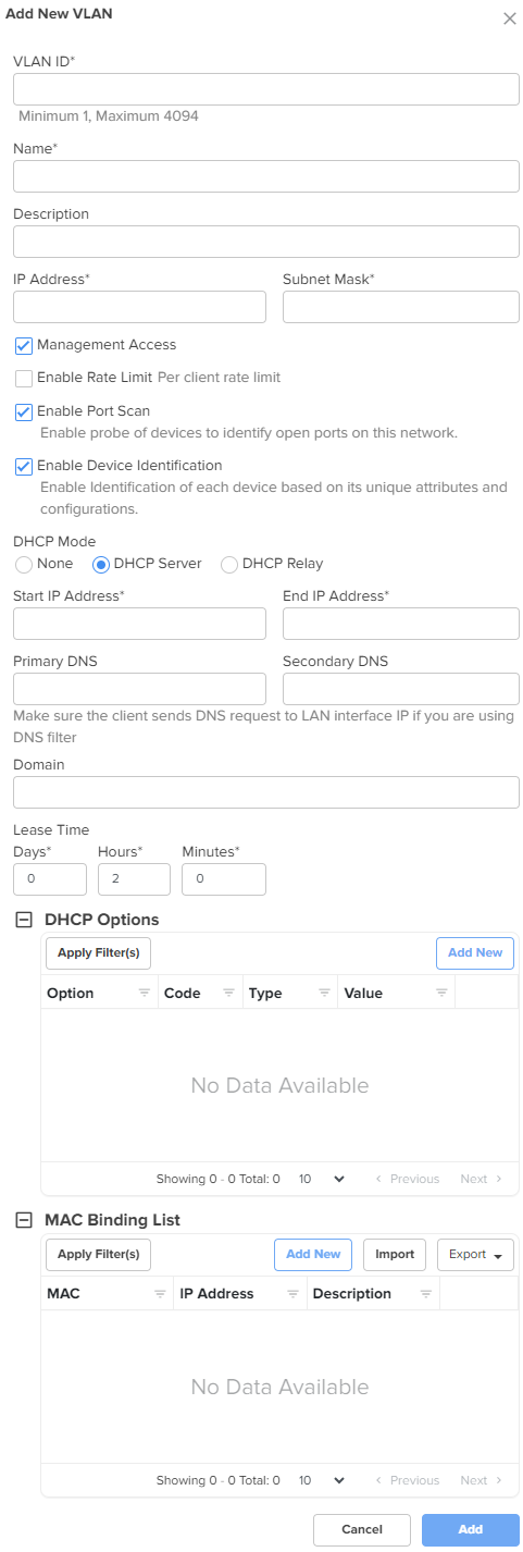
Figure 25 The Add New DHCP Option window
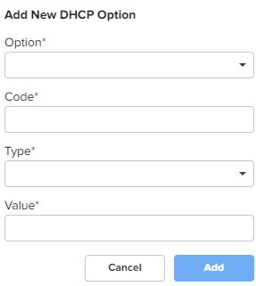
Figure 26 The Add New MAC Binding window
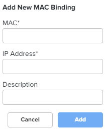
Figure 27 The Import option in MAC Binding List
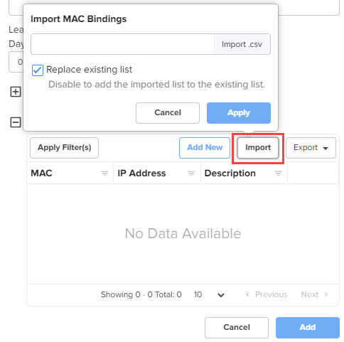
Figure 28 The Export option in MAC Binding List
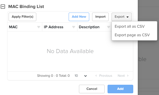
Figure 29 The Add New Route window
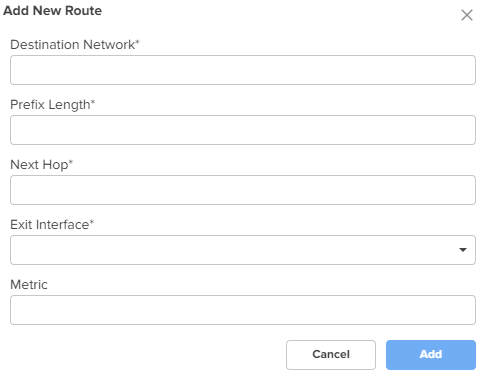
Figure 30 The Add Multiple VLANs window
Click Save.
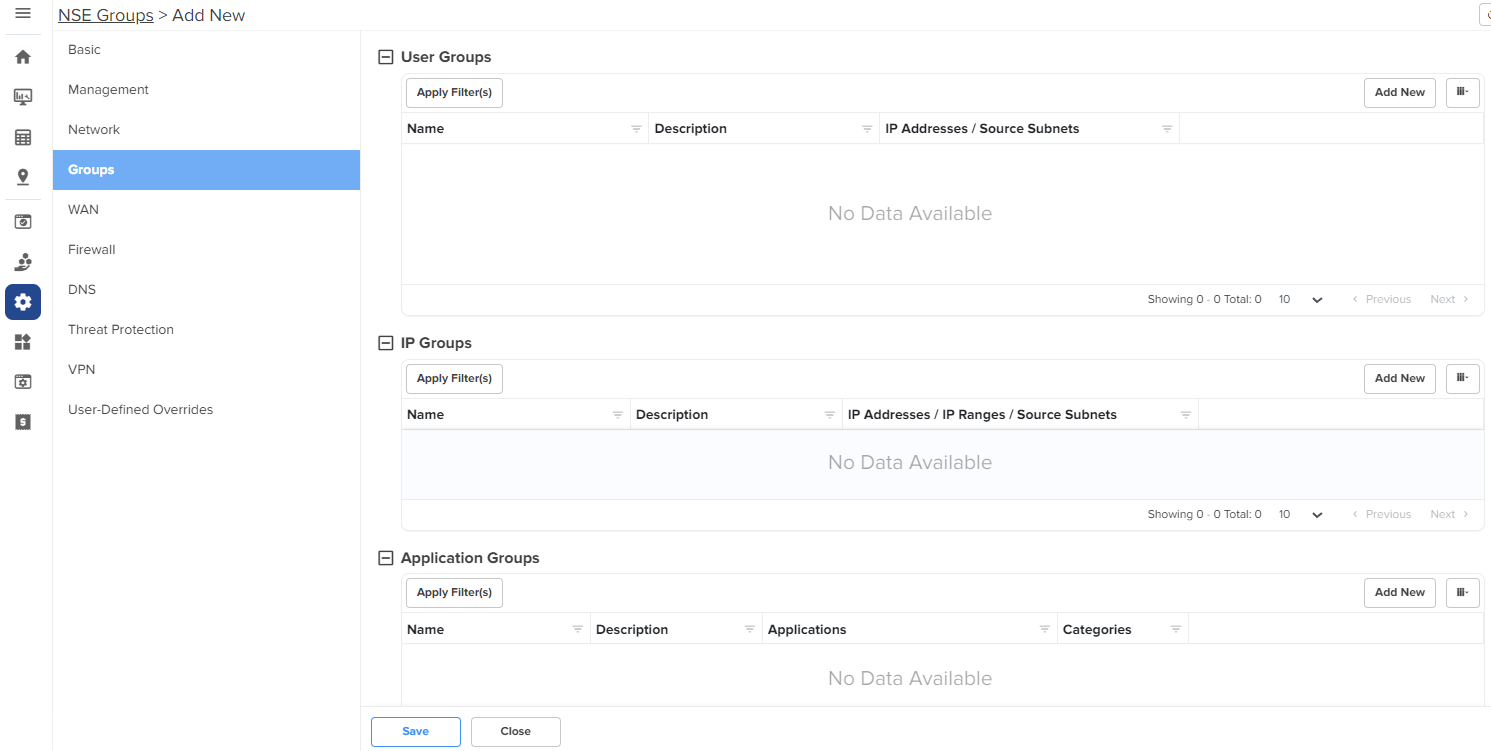
Using the Groups tab, you can configure user groups, IP groups, and application groups.
To view the Groups page, complete the following steps:
On the NSE Groups > Add New page, select the Groups tab.
The Groups page appears, as shown in Figure 31.
Configure the parameters, as described in Table 4.
Table 4 Parameters on the Groups page
| Parameter | Description |
|---|---|
|
On the Groups page, there are User Groups, IP Groups, and ApplicationGroups sections. |
|
|
User Groups User groups are used to group locally configured networks and these groups can be used to associate with policies, especially application rules or DNS rules. To add a new user group, click Add New. The Add User Group window appears, as shown in Figure 32. To edit a user group, click the edit |
|
|
Name |
Name for the user group. This is a mandatory parameter. |
|
Description |
Description for the user group. |
|
IP Addresses/Source Subnets |
IPv4 addresses or source subnets for the user group. This is a mandatory parameter. |
|
IP Groups IP groups are used to group networks originating from the WAN, and can be used to attach port forwarding rules. To add a new IP group, click Add New. The Add IP Group window appears, as shown in Figure 33. To edit an IP group, click the edit |
|
|
Name |
Name for the IP group. |
|
Description |
Description for the IP group. |
|
IP Addresses/IP Ranges/Source Subnets |
IPv4 addresses, IP ranges, or source subnets for the IP group. This is a mandatory parameter. |
|
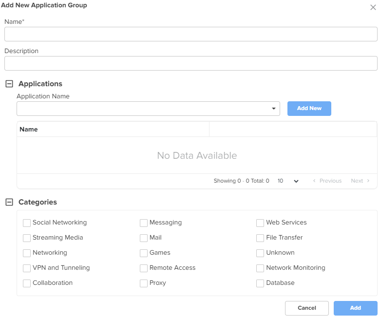
Application Groups Application groups are used to group applications by using application names or categories, which can then be attached to a policy for permitting or denying access. To add a new application group, click Add New. The Add New Application Group window appears, as shown in Figure 34. To edit an application group, click the edit |
|
|
Name |
Name for the application group. |
|
Description |
Description for the application group. |
|
Applications To add applications to the application group, select the required application(s) from the dropdown list and click Add New. The selected applications are added in the Name list. |
|
|
Application Name |
Applications for the new application group. |
|
Categories To include categories for the new application group, select the required categories. |
|
|
Categories |
Categories for the new application group. |
Figure 32 The Add User Group window
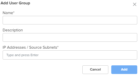
Figure 33 The Add IP Group window
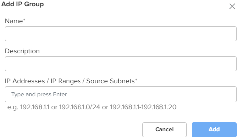
Figure 34 The Add New Application Group window
Click Save.
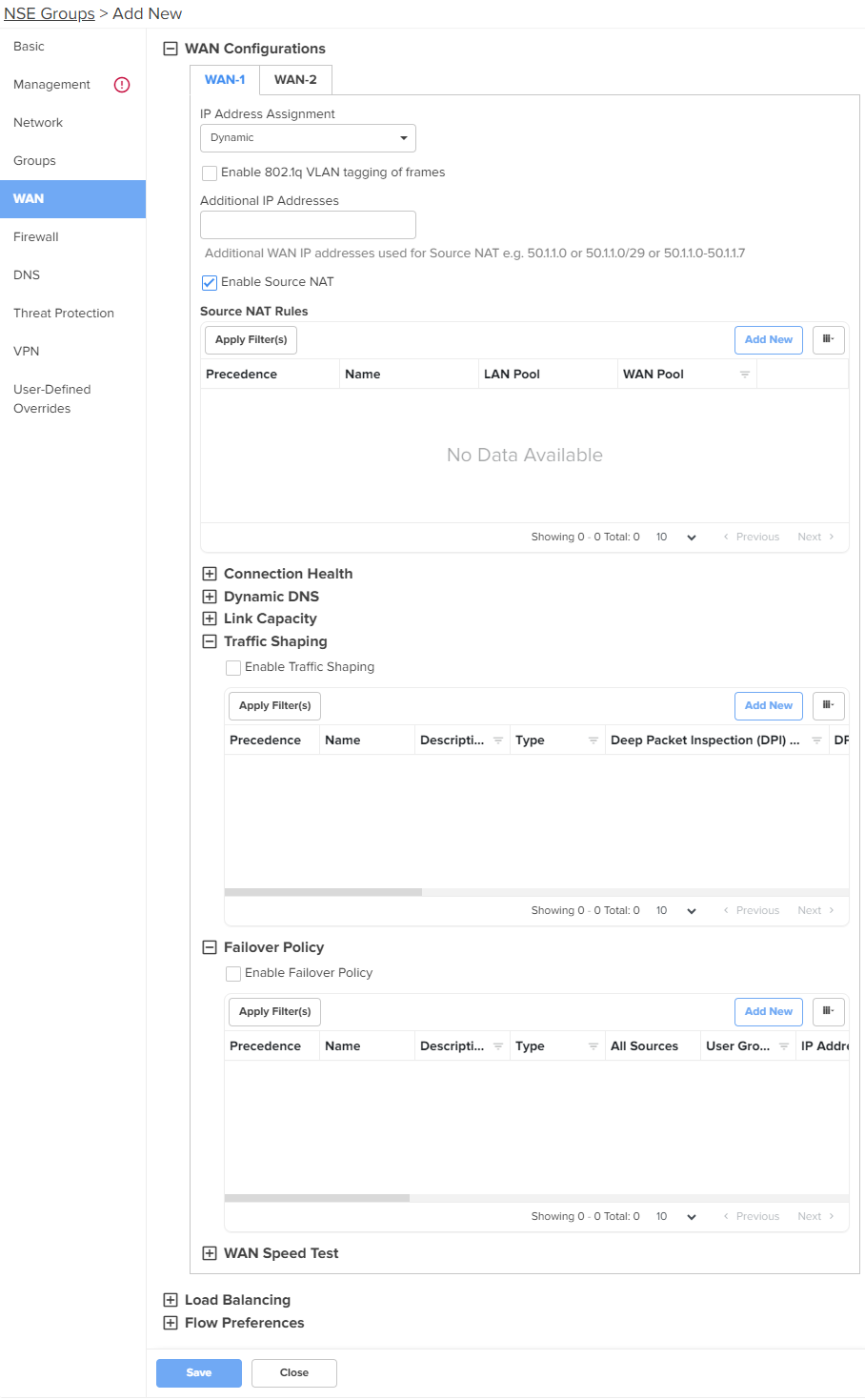
Using the WAN tab, you can configure the settings related to the WAN interface.
To configure parameters on the WAN page, complete the following steps:
On the NSE Groups > Add New page, select the WAN tab.
The WAN page appears.
Figure 35 The WAN page
Configure the parameters, as described in Table 5.
Table 5 Parameters on the WAN page
|
Parameter |
Description |
|---|---|
|
On the WAN page, there are WAN Configurations, LoadBalancing, and Flow Preferences sections. |
|
|
WAN Configurations In this section, you can configure the parameters in Connection Health, Dynamic DNS, Link Capacity, Traffic Shaping, Failover Policy, and WAN Speed Test subsections. The same parameters appear in both WAN-1 and WAN-2 tabs. |
|
|
IP Address Assignment |
Determines the mode of IP address assignment for the WAN interface. The following options are supported:
|
|
Enable 802.1q VLAN tagging of frames |
When this parameter is enabled, 802.1Q tag is inserted with configured VLAN ID for all the packets going out of the WAN interface. By default, this parameter is disabled. |
|
VLAN ID |
This parameter is applicable only when Enable 802.1q VLAN tagging of frames checkbox is selected. VLAN ID range: 1 and 4094. This is a mandatory parameter. When the 802.1Q header is configured, all transmitted frames are expected to include the 802.1Q header with the same VLAN ID. |
|
Following parameters appear when you select Static from the IP Address Assignment dropdown list. |
|
|
IP Address |
The IPv4 address of the WAN interface. This is a mandatory parameter. |
|
IP Address (HA Spare) |
This parameter appears only when Enable HA checkbox is selected from the Basic screen. The IPv4 address of the HA spare. This is a mandatory parameter. |
|
Subnet Mask |
The subnet mask for the IPv4 address of the WAN interface. This is a mandatory parameter. |
|
Default Gateway |
The IPv4 address of the default gateway for the WAN interface. |
|
Primary DNS |
The IPv4 address of primary upstream DNS server on this interface. This is a mandatory parameter. |
|
Secondary DNS |
The IPv4 address of secondary upstream DNS server on this interface. |
|
Following parameters appear when you select PPPoE from the IP Address Assignment dropdown list. |
|
|
Account Controller Name |
Name of the account controller. This parameter allows a maximum of 32 characters. This parameter is optional. |
|
Service Name |
Indicates the service name of the Account Controller. This parameter allows a maximum of 32 characters. The service name configuration is optional. |
|
User |
User name for PPPoE authentication. This is a mandatory parameter. |
|
Password |
Password for PPPoE authentication. This parameter is optional. |
|
MTU |
MTU for PPPoE interface. MTU ranges from 500 to 1492 bytes. Default: 1492 bytes. |
|
TCP MSS Clamping |
Indicates whether TCP MSS Clamping is enabled or disabled. By default, this parameter is enabled. |
|
Additional IP Addresses |
WAN IP addresses that are available for source NAT. Note:The WAN interface supports up to 16 IP addresses. |
|
Enable Source NAT |
Indicates whether the source NAT is enabled or disabled. When enabled, NSE 3000 device will replace the source IP address of the traffic routed from LAN to WAN with the WAN interface IP address. By default, this parameter is enabled. |
|
Source NAT Rules Allows user to configure source NAT rules. User can choose the WAN IP addresses from the Additional IP Address for source NAT. User can configure WAN IP address(es) of their choice for source NAT. By default, all the LAN users' traffic will be source NATed to the configured WAN IP address(es). When LAN pool is configured, the traffic from the specified LAN networks will be source NATed to the configured WAN IP address(es). Note: Source NAT Rules supports up to 16 rules per WAN. To add a new source NAT, click Add New. The Add New Source NAT Rule window appears, as shown in Figure 36. |
|
|
Name |
Name of the Source NAT rule. |
|
Precedence |
The precedence value for the source NAT rule. The precedence value can be between 1 and 150. This is a mandatory parameter. For information about configuring precedence, refer to Configuring rule precedence. |
|
LAN Pool |
The following options are supported:
|
|
WAN Pool |
The following options are supported:
|
|
IP Address |
IPv4 address for the WAN pool. Applicable only when Single IP Address option is selected. |
|
Start IP |
Starting IP address in the range. This parameter is applicable only when Multiple IP Addresses option is selected. This is a mandatory parameter. |
|
End IP |
Ending IP address in the range. This parameter is applicable only when Multiple IP Addresses option is selected. This is a mandatory parameter. |
|
IP Group |
Select the IP group for the source NAT. IP groups are the ones that you configure in the Groups > IP Groups section. This parameter is applicable only when IP Group option is selected. This is a mandatory parameter. |
|
IP Address / Source Subnet |
This parameter is applicable only when IP Address / Source Subnet option is selected. This is a mandatory parameter. |
|
Connection Health This section is configured to monitor the WAN connection health. Click the edit To add a new monitor host, click Add New. The Add New Monitor Host window appears, as shown in Figure 38. |
|
|
Monitor Host |
The hosts used to monitor and collect network traffic data. Default: 8.8.8.8 This is a mandatory parameter. |
|
Number of Host Failures |
The number of monitor hosts that fail to declare the link down. Default value: 1 The maximum number of monitor hosts that can be configured to fail is 5. |
|
Failure Detect Time |
The time period (in seconds) during which the device waits for the response from the monitored host before declaring the link down. Default: 5. Range: 5 to 60 |
|
Interval |
The time interval (in seconds) used by the device to check and reach the monitor hosts. Default: 2. Range: 2 to 10 |
|
Timeout |
The time period (in seconds) the device waits for a response from the monitor host after which the connection is timed out. Default: 2. Range: 1 to 10 |
|
Dynamic DNS |
|
|
Enable Dynamic DNS |
Indicates whether the dynamic DNS for the interface is enabled or disabled. By default, this parameter is disabled. |
|
Following parameters appear when Enable Dynamic DNS checkbox is selected. |
|
|
DNS Provider |
The following options are supported:
By default, Noip option is selected. |
|
DNS Hostname |
Indicates the DNS host name. |
|
Link Capacity |
|
|
Uplink |
The WAN uplink capacity in Mbps. Default: 1000. Range: 1 to 1000 This is a mandatory parameter. |
|
Downlink |
The WAN downlink capacity in Mbps. Default: 1000. Range: 1 to 1000 This is a mandatory parameter. |
|
Traffic Shaping Note: Traffic Shaping supports up to 16 rules per WAN. To add a new traffic shaping rule, click Add New, the Add New Traffic Shaping Rule window appears, as shown in Figure 39. |
|
|
Enable Traffic Shaping |
Indicates whether traffic shaping is enabled or disabled. By default, this parameter is disabled. |
|
Name |
Name of the traffic shaping rule. |
|
Precedence |
The precedence value for the traffic shaping rule. The precedence value can be between 1 and 150. This is a mandatory parameter. For information about configuring precedence, refer to Configuring rule precedence. |
|
Description |
Displays a user-configured description for the traffic shaping rule. |
|
Uplink Bandwidth |
Indicates the uplink bandwidth in Mbps. Range: 1 to 1000 This is a mandatory parameter. |
|
Downlink Bandwidth |
Indicates the downlink bandwidth in Mbps Range: 1 to 1000 This is a mandatory parameter. |
|
DSCP |
Differentiated Services Code Point (DSCP) can range from 0 to 63, with 0 being the lowest priority and 63 being the highest priority. |
|
Type |
Indicates the type of filter rule. The following options are supported:
|
|
Deep Packet Inspection (DPI) Type |
This parameter is applicable only when Type parameter is Application Based. The following options are supported:
This is a mandatory parameter. |
|
DPI Application |
This parameter is applicable only when Deep Packet Inspection (DPI) Type parameter is set to Application. This is a mandatory parameter. |
|
DPI Category |
This parameter is applicable only when Deep Packet Inspection (DPI) Type parameter is set to Category. This is a mandatory parameter. |
|
Protocol |
This parameter is applicable only when Type parameter is IP Based. The following options are supported:
|
|
Source IP Address |
The source IPv4 address for the shaping rule. This is a mandatory parameter. |
|
Mask |
The subnet mask for the shaping rule. This is a mandatory parameter. |
|
Port |
Displays the source port from which IPv4 address messaging is sent. This is a mandatory parameter. |
|
Destination IP Address |
The destination IPv4 address for the shaping rule. This is a mandatory parameter. |
|
Mask |
The subnet mask for the shaping rule. This is a mandatory parameter. |
|
Port |
Displays the destination port to which IPv4 address messaging is sent. This is a mandatory parameter. |
|
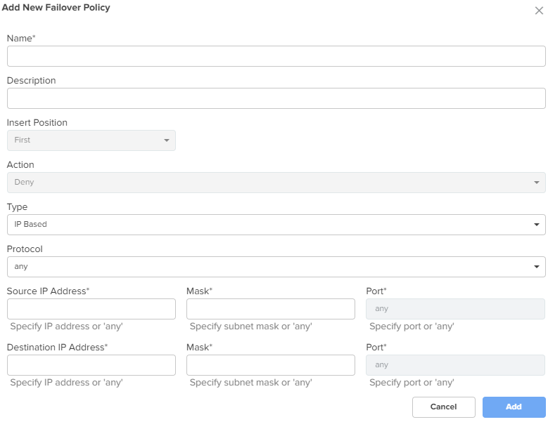
Failover Policy Note: Failover Policy supports up to 32 rules per WAN. To add a new failover policy, click Add New. The Add New Failover Policy window appears, as shown in Figure 40. |
|
|
Enable Failover Policy |
Indicates whether failover policy is enabled or disabled. By default, this parameter is disabled. |
|
Name |
Name of the failover policy. |
|
Precedence |
The precedence value for the failover policy. The precedence value can be between 1 and 150. This is a mandatory parameter. For information about configuring precedence, refer to Configuring rule precedence. |
|
Description |
A description for the policy. |
|
Action |
By default, this parameter is disabled. |
|
Type |
The type of failover rule. The following options are supported:
|
|
Protocol |
This parameter is applicable only when Type parameter is IP Based. The following options are supported:
|
|
Source IP Address |
The source IPv4 address for the failover rule. This is a mandatory parameter. |
|
Mask |
The subnet mask for the failover rule. This is a mandatory parameter. |
|
Port |
The source port for the failover rule. This is a mandatory parameter. |
|
Destination IP Address |
The destination IPv4 address for the failover rule. This is a mandatory parameter. |
|
Mask |
The subnet mask for the failover rule. This is a mandatory parameter. |
|
Port |
Displays the destination port for the failover rule. This is a mandatory parameter. |
|
Deep Packet Inspection (DPI) Type |
This parameter is applicable only when Type parameter is Application Based. The following options are supported:
This is a mandatory parameter. |
|
Apply to |
This parameter is applicable only when Type parameter is Application Based. The following options are supported:
|
|
User Group |
This parameter is applicable when User Group option is selected. This is a mandatory parameter. |
|
IP Address / Source Subnet |
This parameter is applicable when IP Address / Source Subnet option is selected. This is a mandatory parameter. |
|
WAN Speed Test |
|
|
Enable WAN Speed Test |
Enable or disable the WAN speed test. By default, this parameter is disabled. |
Figure 36 The Add New Source NAT Rule window
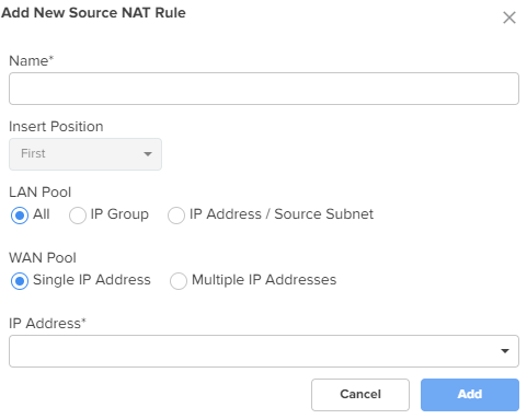
Figure 37 The Edit Monitor Host window
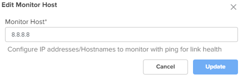
Figure 38 The Add New Monitor Host window
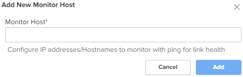
Figure 39 The Add New Traffic Shaping Rule window
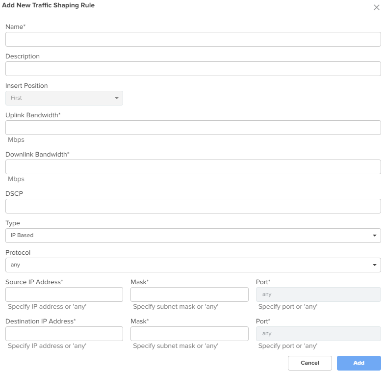
Figure 40 The Add New Failover Policy window
Expand the Load Balancing section and configure the parameters, as described in Table 6.
Table 6 Parameters on the Load Balancing section
|
Parameter |
Description |
|---|---|
|
Load Balancing |
|
|
WAN-1 Mode |
Determines the load balancing mode of device. By default, the WAN-1 Mode parameter is set to Shared. The following options are supported:
|
|
Traffic Share Percentage |
For the Shared mode, the traffic share percentage must be between 5 and 100. This is a mandatory parameter. |
|
WAN-2 Mode |
Determines the load balancing adjust mode of device. By default, the WAN-2 Mode parameter is set to Backup. The following options are supported:
|
|
Traffic Share Percentage |
For the Shared mode, the traffic share percentage between 5 and 100. This is a mandatory parameter. |
Expand the Flow Preferences section and configure the parameters, as described in Table 7.
Table 7 Parameters on the Flow Preferences section
|
Parameter |
Description |
|---|---|
|
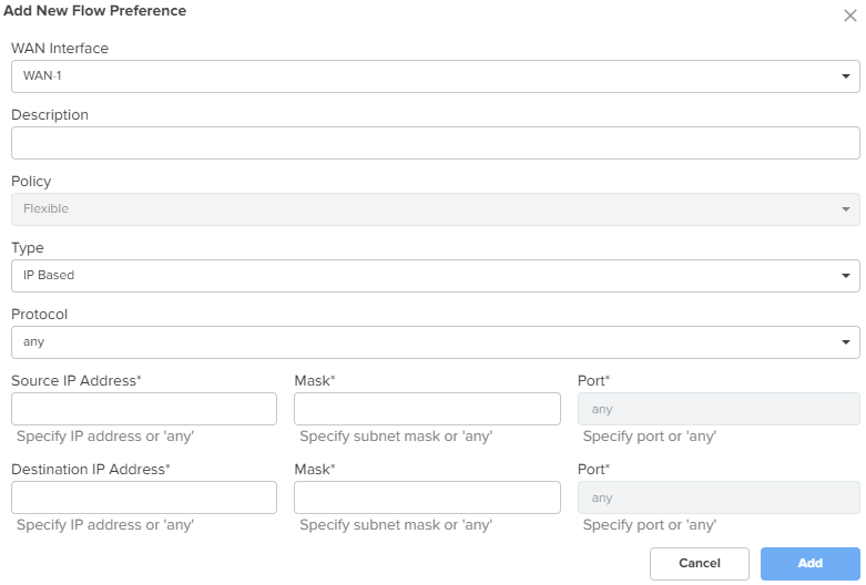
Flow Preferences Flow preferences support up to 30 rules for both WANs combined. To add a new flow preference, click Add New. The Add New Flow Preference window appears, as shown in Figure 41. |
|
|
WAN Interface |
The following options are supported:
|
|
Description |
Provide a description for the flow preference. |
|
Policy |
The flow preference policy. The following options are supported:
|
|
Type |
The flow preference type. The following options are supported:
|
|
Protocol |
This parameter is applicable only when Type parameter is IP Based. The following options are supported:
|
|
Source IP Address |
The source IPv4 address for the flow preference. This is a mandatory parameter. |
|
Mask |
The subnet mask for the flow preference. This is a mandatory parameter. |
|
Port |
The source port for the flow preference. This is a mandatory parameter. |
|
Destination IP Address |
The destination IPv4 address for the flow preference. This is a mandatory parameter. |
|
Mask |
The subnet mask for the flow preference. This is a mandatory parameter. |
|
Port |
The destination port for the flow preference. This is a mandatory parameter. |
|
Deep Packet Inspection (DPI) Type |
This parameter is applicable only when Type parameter is Application Based. The following options are supported:
This is a mandatory parameter. |
|
DPI Application |
This parameter is applicable only when Deep Packet Inspection (DPI) Type parameter is set to Application. This is a mandatory parameter. |
|
DPI Category |
This parameter is applicable only when Deep Packet Inspection (DPI) Type parameter is set to Category. This is a mandatory parameter. |
Figure 41 The Add New Flow Preference window
Click Save.
You can configure precedence for rules in the following configurations:
WAN tab > WAN Configurations > Source NAT Rules
WAN tab > WAN Configurations > Traffic Shaping
WAN tab > WAN Configurations > Failover Policy
Firewall tab > Outbound Filter Rules
To configure rule precedence, complete the following steps:
In the respective configuration sections, click Add New.
The add new window appears.
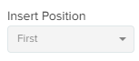
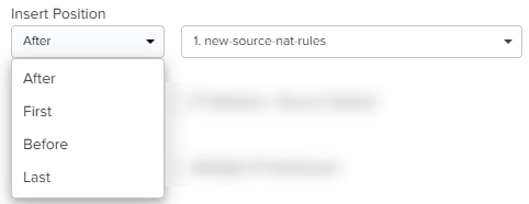
Select the position of the rule from the Insert Position dropdown list. Supported values are First, Last, After, and Before.
For the first rule that is added, this field displays First and the dropdown is disabled.
For subsequent rules that are added, you must select the position and also select the existing rule before or after which you want to place this rule from the adjacent rules dropdown list.
If you select First or Last options (when more than one rule is already existing), then you are not required to select any existing rule.
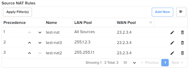
Click Add.
The rules are listed in a table as shown in the image below (sample shown for Source NAT Rules).
To change the order of the rules, perform any of the following steps:
Click the move up ( ) or move down (
 ) arrows corresponding to the rules you want to reorder.
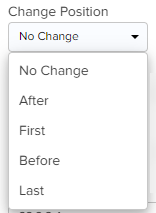
Click the edit (![]() ) icon corresponding to the rule that you want to reorder.
) icon corresponding to the rule that you want to reorder.
In the edit rule window, select the position from the Change Position dropdown list and the corresponding rule.
NSE 3000 firewall allows the user to configure the IP-based and application-based outbound rules, GEO IP filters, port forward rules, one-to-one NAT mappings, and one-to-many NAT mappings. All inbound connections are denied by default. You can configure port forwarding or NAT rules to allow inbound traffic. Outbound traffic is allowed by default. Using application-based outbound rules, users can create rules to block websites without specifying IP addresses or port ranges. Application-based rules allow the user to block a specific type of application within a category or all applications belonging to a category (For example, social messaging).
|
|
Note Up to 150 outbound firewall rules are supported for an NSE Group including combinations of IP-based and application-based rules. |
To configure parameters on the Firewall page, complete the following steps:
On the NSE Groups > Add New page, select the Firewall tab.
The Firewall page appears, as shown in Figure 42.
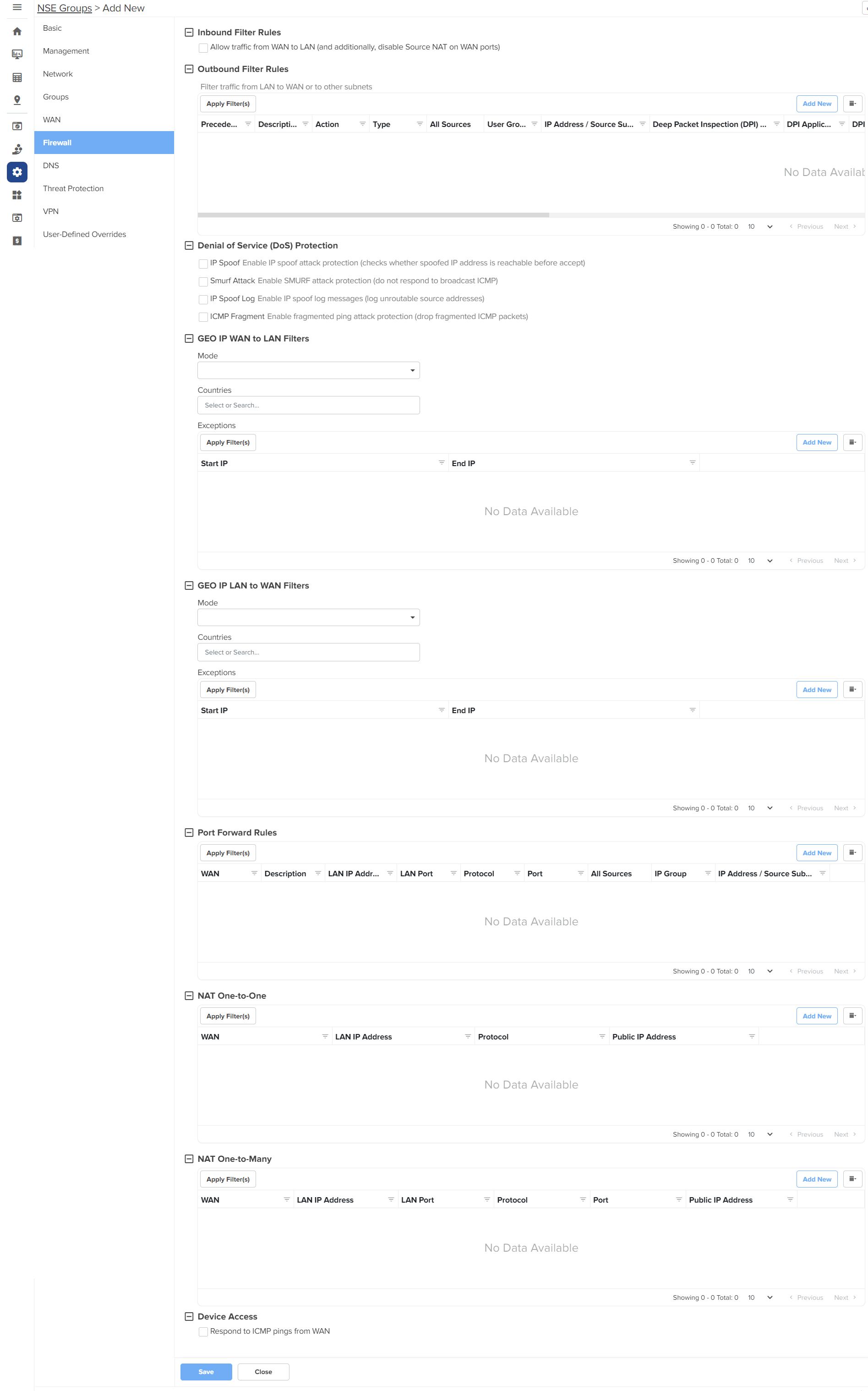
Configure the parameters, as described in Table 8.
Table 8 Parameters on the Firewall page
|
Parameter |
Description |
|---|---|
|
On the Firewall page, there are Inbound Filter Rules, Outbound Filter Rules, Denial of Service (DoS) Protection, GEO IP WAN to LAN Filters, GEO IP LAN to WAN Filters, Port Forward Rules, NAT One-to-One, NAT One-to-Many, and Device Access sections. |
|
|
Inbound Filter Rules By default, NSE firewall routers are configured to function as stateful firewalls by dropping packets that are not related to an established connection. |
|
| Allow traffic from WAN to LAN |
An option to enable or disable the stateful firewall behavior. By default, this parameter is disabled. In special deployment cases, when NSE is positioned behind an MPLS uplink router, you can enable this behavior. To enable this behavior, select the Allow traffic from WAN to LAN checkbox. Additionally, you must disable source NAT on the WAN UI page to allow routing of traffic without NAT, originated on the LAN directed towards the WAN. |
|
Outbound Filter Rules To add a new outbound filter rule, click Add New. The Add New Filter Rule window appears, as shown in Figure 43. |
|
|
Name |
Name of the outbound filter rule. |
|
Precedence |
The precedence value for the filter rule. The precedence value can be between 1 and 150. This is a mandatory parameter. For information about configuring precedence, refer to Configuring rule precedence. |
|
Description |
Displays a user-configured description for the filter rule. |
|
Action |
Determines the action of filter. The following options are supported:
|
|
Type |
The type of filter rule. The following options are supported:
|
|
Protocol |
This parameter is applicable only when Type parameter is IP Based. The following options are supported:
|
|
Source IP Address |
The source IPv4 address for the filter rule. This is a mandatory parameter. |
|
Mask |
The source subnet mask for the filter rule. This is a mandatory parameter. |
|
Port |
This parameter is applicable only when Protocol parameter is TCP or UDP. Supported values: 1 to 65535 or any Supports a single port number or a port range, for example, 3-10. This is a mandatory parameter. |
|
Destination IP Address |
The destination IPv4 address for the filter rule. This is a mandatory parameter. |
|
Mask |
The destination subnet mask for the filter rule. This is a mandatory parameter. |
|
Port |
This parameter is applicable only when Protocol parameter is TCP or UDP. Supported values: 1 to 65535 or any Supports a single port number or a port range, for example, 3-10. This is a mandatory parameter. |
|
Deep Packet Inspection (DPI) Type |
This parameter is applicable only when Type parameter is Application Based. The following options are supported:
This is a mandatory parameter. |
|
DPI Application |
This parameter is applicable only when DPI Type parameter is set to Application. This is a mandatory parameter. |
|
DPI Category |
This parameter is applicable only when DPI Type parameter is set to Category. This is a mandatory parameter. |
|
Apply to |
This parameter is applicable only when Type parameter is Application Based. The following options are supported:
|
|
User Group |
This parameter is applicable when User Group option is selected. This is a mandatory parameter. |
|
IP Address / Source Subnet |
This parameter is applicable when IP Address / Source Subnet option is selected. This is a mandatory parameter. |
|
Denial of Service (DoS) Protection |
|
|
IP Spoof |
Enable or disable the IP spoof attack protection. By default, this parameter is disabled. |
|
Smurf Attack |
Enable or disable the smurf attack protection. By default, this parameter is disabled. |
|
IP Spoof Log |
Enable or disable IP spoof log messages. By default, this parameter is disabled. |
|
ICMP Fragment |
Enable or disable the fragmented ping attack. By default, this parameter is disabled. |
|
GEO IP WAN to LAN Filters GEO IP WAN to LAN filters allows users to configure rules to permit/deny traffic based on the source country of inbound traffic. |
|
|
Mode |
Specifies the mode for GEO IP WAN to LAN filters. The following options are supported:
|
|
Countries |
The source countries from which the traffic originates. |
|
Exceptions Exceptions allow users to configure source IP address ranges that are allowed in the inbound traffic. To add a new exception, click Add New. The Add New Exception window appears, as shown in Figure 44. |
|
|
Start IP |
Starting IPv4 address in the range. This is a mandatory parameter. |
|
End IP |
Ending IPv4 address in the range. This is a mandatory parameter. |
|
GEO IP LAN to WAN Filters GEO IP LAN to WAN Filters allows users to configure rules to permit/deny traffic based on the destination country of outbound traffic. |
|
|
Mode |
Specifies the mode for GEO IP LAN to WAN filters. The following options are supported:
|
|
Countries |
The destination countries to which the traffic is destined. |
|
Exceptions Exceptions allow users to configure destination IPv4 address ranges that are allowed in the outbound traffic. To add a new exception, click Add New. The Add New Exception window appears, as shown in Figure 44. |
|
|
Start IP |
Starting IPv4 address in the range. This is a mandatory parameter. |
|
End IP |
Ending IPv4 address in the range. This is a mandatory parameter. |
|
Port Forward Rules Port Forward Rules allow users to forward traffic destined to the WAN Interface IP address of NSE 3000 on a specific TCP or UDP port to any of the LAN IP address. Port Forward Rules provides remote access to internal resources. To add a new port forward rule, click Add New. The Add New Port Forward Rule window appears, as shown in Figure 45. |
|
|
WAN |
The interface to forward inbound traffic to the internal host. The following options are supported:
|
|
Description |
Displays the user-configured description for the port forward rule. |
|
LAN IP Address |
The IPv4 address to which traffic will be forwarded. This is a mandatory parameter. |
|
LAN Port |
The LAN port to which the traffic will be forwarded. Supported values: 1 to 65535. This is a mandatory parameter. |
|
Protocol |
The protocol of forwarded traffic. The following options are supported:
|
|
Port |
The destination port of the incoming traffic on the WAN interface. Supported values: 1 to 65535. This is a mandatory parameter. |
|
Apply To |
The following options are supported:
|
|
IP Group |
This parameter is applicable only when IP Group option is selected. |
|
IP Address / Source Subnet |
This parameter is applicable only when IP Address / Source Subnet option is selected. This is a mandatory parameter. |
|
NAT One-to-One NAT One-to-One allows users to map an IP address on the WAN side to a LAN IP address. The IP address on the WAN side should be different from any of the WAN interface (WAN-1/WAN-2) IP addresses. NAT One-to-One rules provide remote access to any of the LAN resources. To add a new NAT one-to-one, click Add New. The Add New NAT One-to-One window appears, as shown in Figure 46. |
|
|
WAN |
The following options are supported:
|
|
Public IP Address |
The public IPv4 address on the WAN side that is used to access the LAN resource. The public IPv4 address is different from the IPv4 address of the WAN (WAN-1/WAN-2) interfaces. This is a mandatory parameter. |
|
LAN IP Address |
The LAN IPv4 address of the server which is hosting the resource. This is a mandatory parameter. |
|
Protocol |
The protocol of the incoming traffic. The following options are supported:
|
|
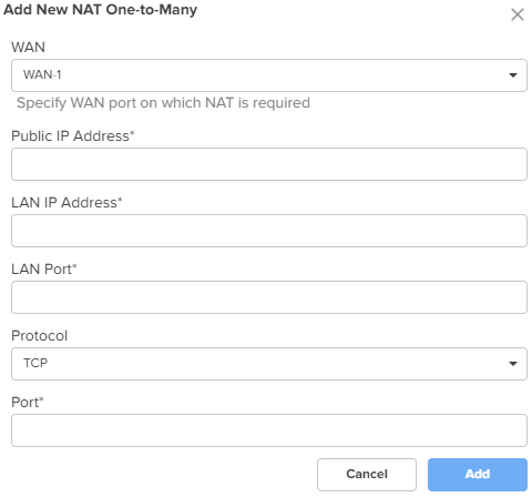
NAT One-to-Many NAT One-to-Many provides remote access to internal resources. It maps a public IP address to multiple LAN IPs and ports. To add a new NAT one-to-many, click Add New, the Add New NAT One-to-Many window appears, as shown in Figure 47. |
|
|
WAN |
The following options are supported:
|
|
Public IP Address |
The public IPv4 address on the WAN side that is used to access the LAN resource. The public IPv4 address is different from the IPv4 address of the WAN (WAN-1/WAN-2) interfaces. This is a mandatory parameter. |
|
LAN IP Address |
The LAN IPv4 address of the server which is hosting the resource. This is a mandatory parameter. |
|
LAN Port |
The LAN Port which is hosting the resource. Supports a single port number or a port range, for example, 3-10. This is a mandatory parameter. |
|
Protocol |
The protocol of the incoming traffic. The following options are supported:
|
|
Port |
The destination port of the incoming traffic on the WAN interface. This is a mandatory parameter. |
|
Device Access |
|
|
Respond to ICMP pings from WAN |
This parameter is disabled by default. When enabled, this service is enabled for all the sources, unless specific IP addresses or IP groups are configured in the IP Group and IP Address / Source Subnet parameters. |
|
IP Group |
Specifies the IP group for this service. |
|
IP Address / Source Subnet |
Specifies the IPv4 address or source subnet for this service. |
Figure 43 The Add New Filter Rule window
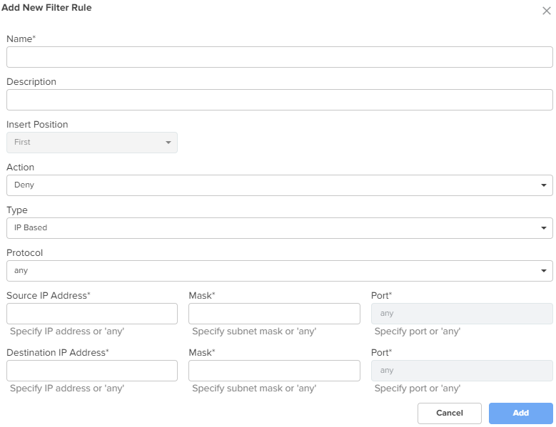
Figure 44 The Add New Exception window
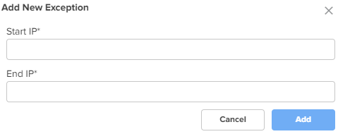
Figure 45 The Add New Port Forward Rule window
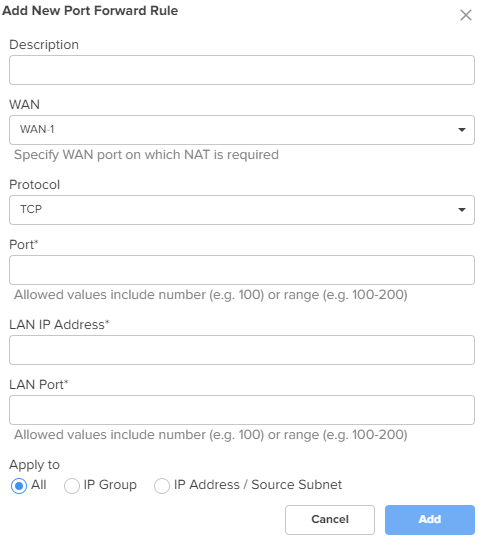
Figure 46 The Add New NAT One-to-One window
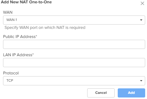
Figure 47 The Add New NAT One-to-Many window
Click Save.
NSE 3000 supports DNS-based filters. DNS-based filters allow users to block certain category of websites. From the blocked list, users can still allow certain websites by adding them to the exception list. For example, if user blocks social-media category then all the social websites will be blocked including linkedin.com since linkedin.com belongs to social-media category. Adding linkedin.com to the Exception to filters list will allow access to linkedin.com while blocking other social-media websites.
To configure parameters on the DNS page, complete the following steps:
On the NSE Groups > Add New page, select the DNS tab.
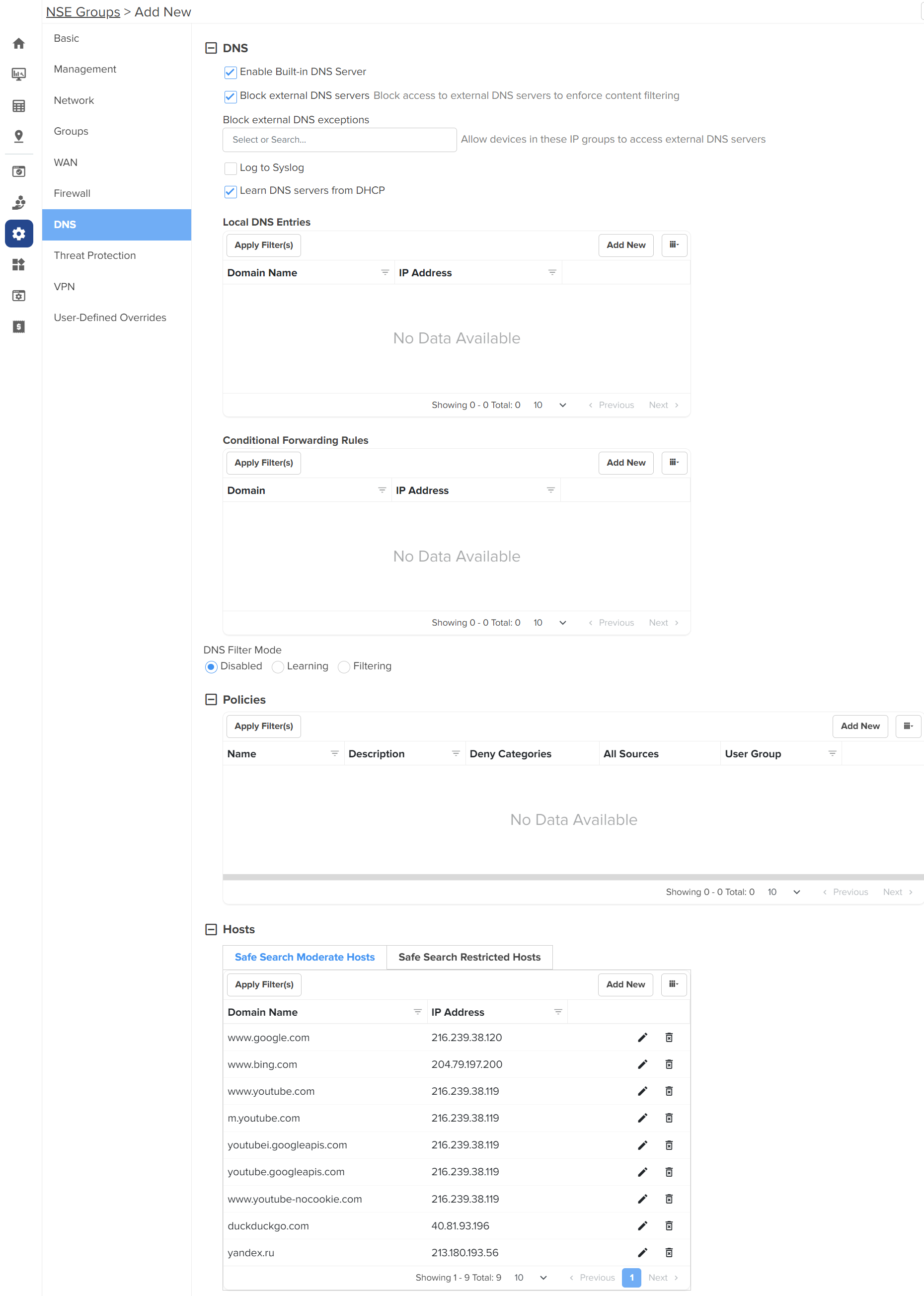
The DNS page appears, as shown in Figure 48.
Configure the parameters, as described in Table 9.
Table 9 Parameters on the DNS page
|
Parameter |
Description |
|---|---|
|
On the DNS page, there are DNS, Policies, and Hosts sections. |
|
|
DNS |
|
|
Enable Built-in DNS Server |
Indicates whether the on-board DNS server is enabled or disabled. By default, this parameter is enabled. |
|
Block external DNS servers |
Blocks the client to reach to any external DNS servers. By default, this parameter is enabled. |
|
Block external DNS exceptions |
Allows the clients added in the exceptions list to reach to any external DNS servers. |
|
Log to Syslog |
Specifies whether the DNS queries received from the client is logged to an external syslog server. |
|
Learn DNS servers from DHCP |
Dynamically learns the DNS server IP on WAN. By default, this parameter is enabled. When you disable this parameter, the Primary DNS and Secondary DNS parameters are displayed. |
|
Primary DNS |
The IPv4 address of the primary upstream DNS server. |
|
Secondary DNS |
The IPv4 address of the secondary upstream DNS server. |
|
Local DNS Entries To add a new local host, click Add New. The Add New Local Host window appears, as shown in Figure 49. |
|
|
Domain |
A domain name for the local host. This is a mandatory parameter. |
|
IP address |
The IPv4 address of the local host. This is a mandatory parameter. |
|
Conditional Forwarding Rules To add a new forwarding rule, click Add New. The Add New Forwarding Rule window appears, as shown in Figure 50. |
|
|
Domain |
A domain name for the forwarding rule. This is a mandatory parameter. |
|
IP address |
The IPv4 address of the server to which the DNS query is forwarded. |
|
DNS Filter Mode |
Specifies the mode for DNS filtering. The following options are supported:
|
|
Policies To add a new policy, click Add New. The Add New Policy window appears, as shown in Figure 51. |
|
|
Name |
Name for the policy. This is a mandatory parameter. |
|
Description |
Description about the policy. |
|
Deny categories |
Categories to deny in the following sections:
Expand the sections and select individual categories. To select all categories in a section, select the checkbox provided for the section. |
|
Safe Search Mode |
The following options are supported:
|
|
Allow Exceptions (List of Domain Names) |
Enter the exempted domain names separated by a comma (,). |
|
Apply to |
The following options are supported:
|
|
User Group |
This parameter is applicable only when User Group option is selected for Apply to parameter. This is a mandatory parameter. |
|
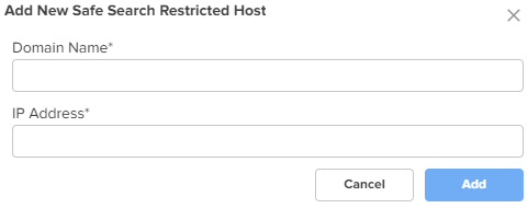
Hosts Hosts section contains two tabs - Safe Search Moderate Hosts and Safe Search Restricted Hosts The following parameters appear in both the tabs and can be configured as required. A list of hosts are already added by default. You can modify these hosts by clicking the edit |
|
|
Domain Name |
The domain name for the safe search host This is a mandatory parameter. |
|
IP address |
The IPv4 address of the safe search host. This is a mandatory parameter. |
Figure 49 The Add New Local Host window
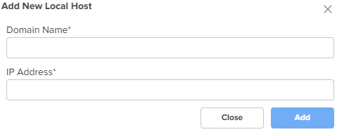
Figure 50 The Add New Forwarding Rule window
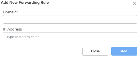
Figure 51 The Add New Policy window
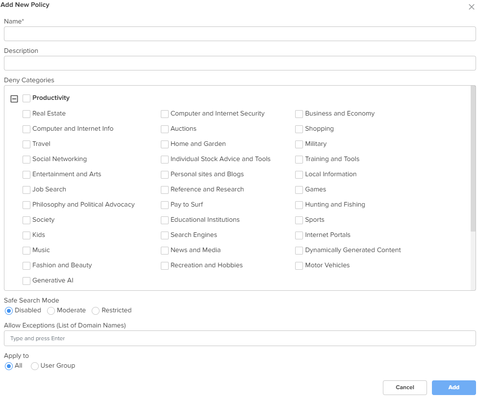
Figure 52 The Add New Safe Search Moderate Host
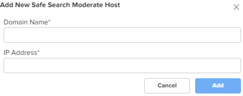
Figure 53 The Add New Safe Search Restricted Host
Click Save.
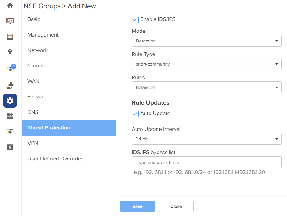
Using the Threat Protection tab, you can configure the Intrusion Detection and Prevention system (IDS/IPS) parameters.
NSE 3000 supports IDS/IPS engine. IPS engine uses a series of rules that help define a malicious network activity. IPS engine supports rules from snort and emerging threats. The solution supports both community and licensed rules. The IPS engine uses these rules to find packets that match against them and generates alerts for users.
To configure parameters on the Threat Protection page, complete the following steps:
On the NSE Groups > Add New page, select the Threat Protection tab.
The Threat Protection page appears, as shown in Figure 54.
Figure 54 The Threat Protection page
Configure the parameters, as described in Table 10.
Table 10 Parameters on the Threat Protection page
|
Parameter |
Description |
|---|---|
|
IDS/IPS |
|
|
Enable IDS/IPS |
Indicates whether IDS/IPS is enabled or disabled. By default, this parameter is enabled only in new NSE groups. When this parameter is enabled, the following default settings apply:
|
|
Mode |
Specifies the IDS/IPS mode. The following options are supported:
|
|
Rule Type |
Specifies the IDS/IPS rule type. The following options are supported:
|
|
Rules |
Specifies the IDS/IPS rule policy. This parameter is applicable when Rule Type is snort-vrt or snort-community. The following options are supported:
|
|
Oink Code |
This parameter is applicable when Rule Type is snort-vrt or emergency- threats pro. |
|
Category |
Categories to select from the Category section. This parameter is applicable when Rule Type is snort-vrt, emerging-threats open, or emerging-threats pro. Note: The categories are same for emerging-threats open and emerging-threats pro rule types. You can select or clear all categories by using the Category checkbox. |
|
Rule Updates |
|
|
Auto Update |
Indicates whether the IDS/IPS rules must be automatically updated or not. By default, this parameter is enabled. When Auto Update is enabled, NSE 3000 will periodically download and activate the IDS/IPS rules. |
|
Auto Update Interval |
Time interval for the periodic updates of IDS/IPS rules. The following options are supported:
By default, the 24 Hrs option is selected. |
|
IDS/IPS bypass list |
List of allowed IPv4 addresses or range of allowed IPv4 addresses. IDS/IPS operating in prevention mode blocks traffic from a host on detecting malicious traffic from the host. When an IPv4 address is part of allowed IP addresses, IDS/IPS will not block traffic from the host even when malicious traffic is detected. |
Click Save.
NSE 3000 provides an on-board VPN server that allows remote users to establish a connection using the native VPN client supported in most of the operating systems. The VPN server uses the L2TP/IPsec protocol with the IPsec encryption and hashing algorithms. The VPN server maintains a pool of IP addresses and leases the IP addresses from this pool for remote users.
NSE 3000 also provides an on-board RADIUS server that allows authentication and accounting of enterprise and remote users. The RADIUS server maintains user profiles in a central database.
The VPN page allows to set the following configurations:
IPsec tunnel is a VPN technology that provides a secure, encrypted connection between two devices or networks over the internet or another public network. It uses IPsec protocols to encrypt the traffic between two endpoints, making it difficult for anyone to intercept the communication.
IPsec site-to-site tunnel is used to connect two remote sites for secure communications. NSE allows setting up tunnels both in responder mode and initiator mode. Both, IKEv1 and IKEv2 are supported in the configuration. The default version is IKEv2.
|
|
Note You can configure up to 100 IPsec site-to-site tunnels. |
Pre-shared key is the authentication method supported by the NSE device. Each site can have its own pre-shared key. The site is identified by an identifier (string or the IP address of the site). Each site has to be configured with a local and remote site for the tunnel to establish.
|
|
Note NSE supports VPN translation for a Site-to-Site configuration. The local subnets that are advertised to peers are configured to translate to a different equally sized subnet. This is useful in deployments where the same local subnet is used in multiple locations. For example, the 192.168.200.0/24 network can be found in multiple locations as it is the default network configuration. If 192.168.200.0/24 is available in multiple locations, this can be configured to be translated to 10.10.10.0/24. to prevent address conflicts, The translation can also be 1 to M. In case of 1 to M, 192.168.200.0/24 can be configured to be translated to 10.10.10.10/32. |
You can perform the following configurations:
To enable a site-to-Site VPN and configure the settings, complete the following steps:
On the NSE Groups>Add New page, select the VPN tab.
The VPN page appears, as shown in Figure 55.
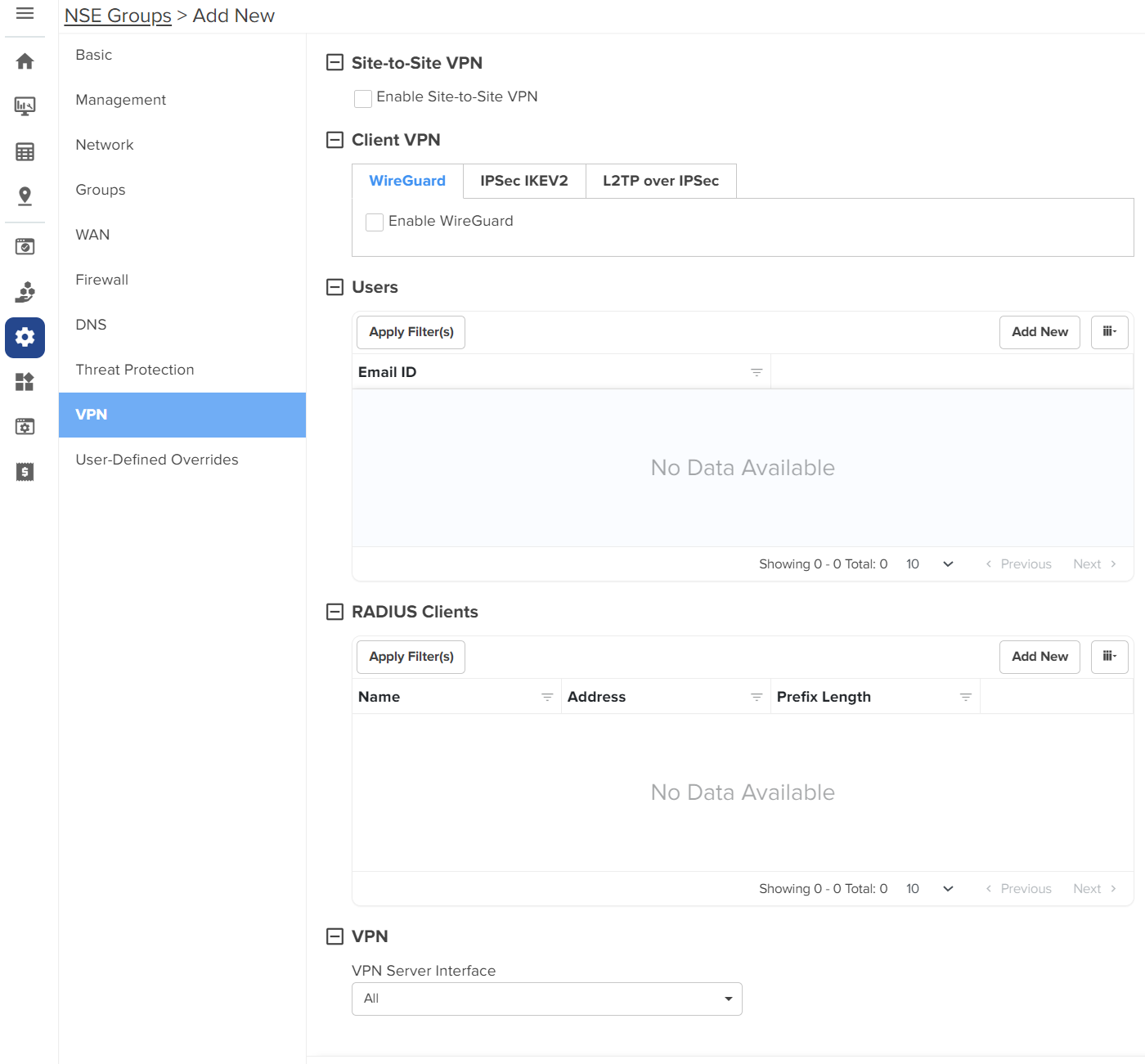
In the Site-to-Site VPN section, select the Enable Site-to-Site VPN checkbox to enable the site-to-site VPN configuration. By default, it is disabled. When you enable site-to-site VPN, you are allowed to add a new site-to-site VPN and configure parameters.
To add a new site-to-site VPN, click Add New. The Add New Site-to-Site VPN window appears, as shown in Figure 56.
Figure 56 The Add New Site-to-Site VPN window
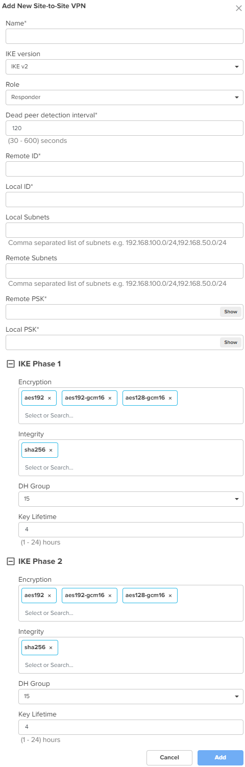
Configure the parameters, as described in Table 11.
Table 11 Parameters for the Site-to-Site VPN configuration
|
Parameter |
Description |
|---|---|
|
Name |
A name for the new site-to-site VPN. This is a mandatory parameter. |
|
IKE version |
The Internet Key Exchange (IKE) version for the site-to-site VPN. The following options are supported:
|
|
Role |
Specifies the role for the tunnels. The following options are supported:
Default role: Responder |
|
Dead peer detection interval |
The interval (in seconds) for detecting dead peers. Range: 30 - 600 seconds. Default: 120 seconds This is a mandatory parameter. |
|
Remote ID |
The remote ID. The value of 192.168.50.10 is pre-configured and is not modifiable. This is a mandatory parameter. |
|
Local ID |
The local ID. This is a mandatory parameter. |
|
Local Subnets |
This is a mandatory parameter. This parameter allows you to add multiple local subnets. To add new local subnets, complete the following steps:
|
|
Remote Subnets |
The comma-separated list of remote subnets. This is a mandatory parameter. |
|
Remote PSK |
The remote PSK. This is a mandatory parameter. |
|
Local PSK |
The local PSK. This is a mandatory parameter. |
|
The following parameters are common for both IKE Phase 1 and IKE Phase 2. |
|
|
Encryption |
The following options are supported:
|
|
Integrity |
The following options are supported:
|
|
DH Group |
The following options are supported:
|
|
Key Lifetime |
The duration (in hours) for the pre-shared key. Range: 1 to 24 |
Click Add. The new site-to-site VPN is added.
Click Save on the Add New page to apply the changes.
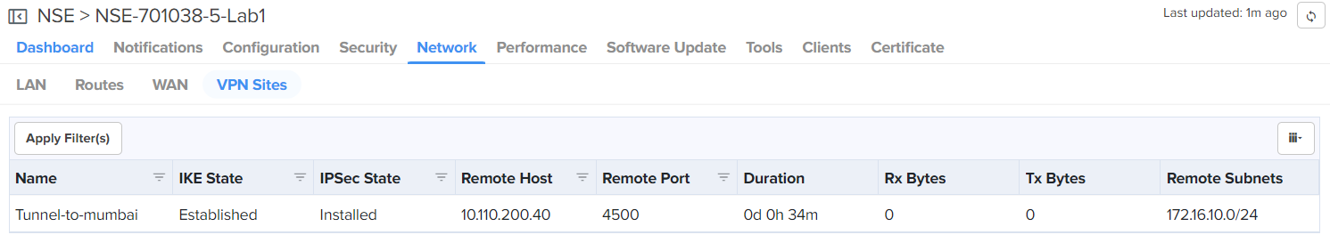
To view the IPsec tunnel statistics, navigate to the NSE Group > Network > VPN Sites tab, as shown in Figure 57.
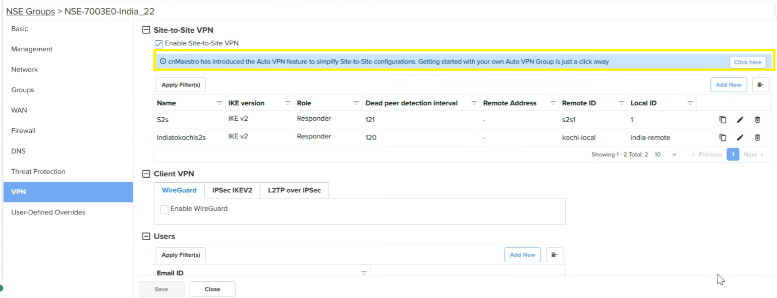
Currently, NSE 3000 supports 100 site-to-site VPN tunnels, However, cnMaestro allows the Auto VPN configuration to simplify Site-to-Site configuration. The Auto VPN configuration is useful for device-level configuration, device-level monitoring, and debugging.
Consider the following key points:
If there is an NSE device for which the Auto VPN is not configured, the Site-to-Site VPN section on the VPN page displays a message (as shown in Figure 58). This message indicates that you can add the Auto VPN configuration for this NSE device. When you configure an auto VPN group using the Configuration > NSE Profiles > Auto VPN page, the Site-to-Site VPN configuration changes are disabled for the NSE device.
Figure 58 The site-to-site VPN configuration before switching to Auto VPN
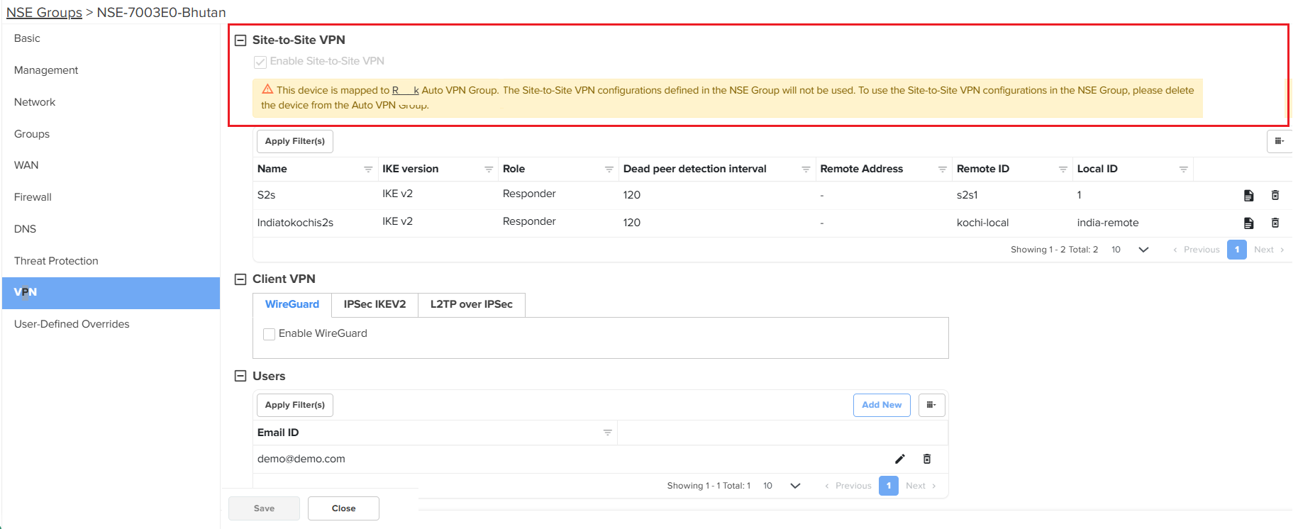
If the sites are already added to an Auto VPN group, then you cannot use the Site-to-Site VPN configuration. A message is displayed in the Site-to-Site VPN section on the VPN page (as shown in Figure 59). You must delete the NSE device from the Auto VPN group on the Auto VPN page to use the Site-to-Site VPN configuration.
|
|
Note You CANNOT configure a site-to-site VPN for the NSE 3000 device on which auto VPN is configured. You must delink the devices from Auto VPN group and then configure the Site-to-Site VPN feature. |
Figure 59 The site-to-site VPN configuration after switching to Auto VPN
To configure Client VPN specific parameters on the VPN page, complete the following steps:
On the VPN page (as shown in Figure 55), go to the Client VPN section.
The Client VPN section contains the following tabs:
WireGuard: A VPN protocol that is highly secure.It is simpler and more efficient than traditional IPSec. It is simpler and more efficient than traditional IPSec.
Configure the parameters, as described in Table 12.
Table 12 Parameters for the Client VPN configuration
When you enable two-factor authentication (2FA), scan the QR code to add a 16-digit key to a particular user's Google Authenticator app.
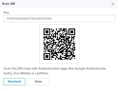
An email is also sent to the configured email address with the QR code and the 16-digit key. The two-factor authentication gets enabled for the user when the user tries to connect to the NSE 3000 device using the remote VPN client from the WAN side. Users on the LAN side do not require two-factor authentication (2FA).
Click Save on the Add New page to add the changes.
The Users section on the VPN page is common for all the three protocols - WireGuard, IPSec IKEV2, and L2TP over IPSec. To configure user specific parameters on the VPN page, complete the following steps:
On the VPN page (as shown in Figure 55), go to the Users section.
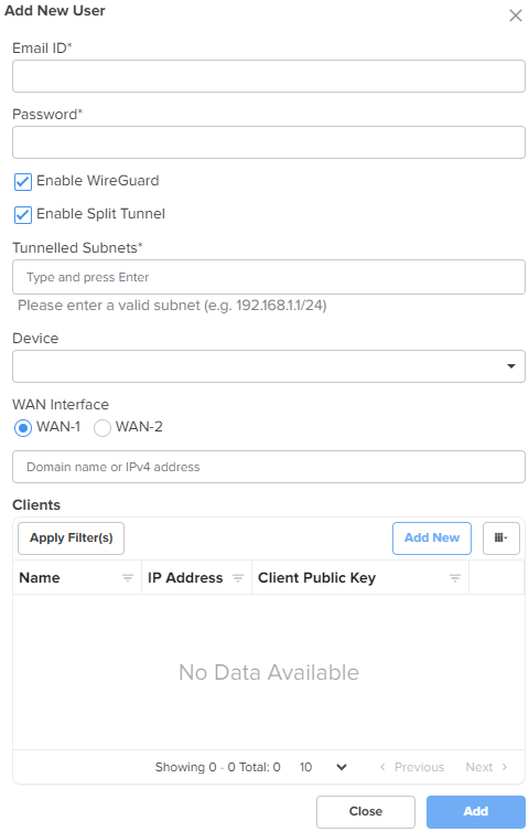
To add a new user, click Add New. The Add New User window appears, as shown in Figure 60.
Figure 60 The Add New User window
Configure the parameters, as described in Table 13.
Table 13 Parameters for the user configuration
|
Parameter |
Description |
|---|---|
|
Users |
|
|
Email ID |
Email ID of the user. This is a mandatory parameter. |
|
Password |
Password for the user. This is a mandatory parameter. |
|
Enable WireGuard |
Indicates whether WireGuard is enabled or disabled. This parameter is visible on the Add New User window only if you have selected the Enable WireGuard checkbox in the Client VPN section. By default, this parameter is disabled. |
|
Following parameters appear when Enable WireGuard checkbox is selected in the Add New User window. |
|
|
Enable Split Tunnel |
Indicates whether split tunnel is enabled or disabled. By default, this parameter is enabled. |
|
Tunnelled Subnets |
Specifies the list of local subnets in NSE that should be allowed access from the WireGuard clients. |
|
Device |
Indicates the NSE 3000 device. When you select an NSE 3000 device, the device's public key is populated in the[Peer]section of the WireGuard client configuration file. This is a mandatory parameter. |
|
WAN Interface |
WAN Interface of the NSE 3000 device. When you select a WAN interface, the NSE 3000 device's WAN IP is populated as the endpoint IP in the [Peer] section of the WireGuard client configuration file. The following WAN Interface options are supported:
|
|
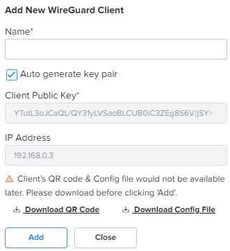
Clients: In this section, you have an option to add a new WireGuard client. To add a new WireGuard client, click Add New. The Add New WireGuard Client window appears, as shown in Figure 61. |
|
|
Name |
Name for the new WireGuard client. This is a mandatory parameter. |
|
Auto generate key pair |
Generates a public and private key pair for the client. By default, this parameter is enabled. When this option is enabled, the Client Public Key field is auto-populated with the public key generated for that client. When this option is disabled, you need to provide the WireGuard client public key generated on the WireGuard client device. |
|
Client Public Key |
Public key of the client. This is a mandatory parameter. |
|
IP Address |
Auto-generated IP address of the WireGuard client. |
|
Note: You have options to download QR code and configuration file in the Add New WireGuard Client window, as shown in Figure 61. |
|
Figure 61 The Add New WireGuard client window
Click Add. The user configuration is added.
Click Save on the Add New page to apply the changes.
To set the RADIUS client configuration on the VPN page, complete the following steps:
On the VPN page (as shown in Figure 55), go to the RADIUS Clients section.
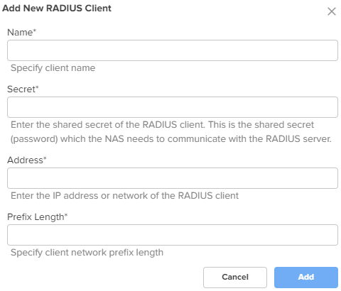
To add a new RADIUS client, click Add New. The Add New RADIUS Client window appears, as shown in Figure 62.
Figure 62 The Add New RADIUS Client window
Configure the parameters, as described in Table 14.
Table 14 Parameters for the RADIUS Client configuration
|
Parameter |
Description |
|---|---|
|
RADIUS Clients |
|
|
Name |
Name of the RADIUS client. This is a mandatory parameter. |
|
Secret |
The shared secret of the RADIUS client. This is the shared secret (password) that the NAS needs to communicate with the RADIUS server. This is a mandatory parameter. |
|
Address |
The IPv4 address or network address of the RADIUS client. This is a mandatory parameter. |
|
Prefix Length |
The client network prefix length. This is a mandatory parameter. |
Click Add on the Add New RADIUS Client window.
Click Save onthe Add New page to add the changes.
To configure the VPN Server interface, complete the following steps:
On the VPN page (as shown in Figure 55), go to the VPN section.
The VPN Server Interface dropdown list is visible. This parameter displays the following options:
WAN-1 - The first WAN interface on your server.
WAN-2 - The second WAN interface on your server.
All - Applies to all WAN interfaces.
Select the required option from the dropdown list.
Click Save on the Add New page to add the changes.
Using the User-Defined Overrides tab, you can configure the user-defined overrides.
To configure parameters on the User-Defined Overrides page, complete the following steps:
On the NSE Groups > Add New page, select the User-Defined Overrides tab.
The User-Defined Overrides page appears, as shown in Figure 63.
Figure 63 The User-Defined Overrides page
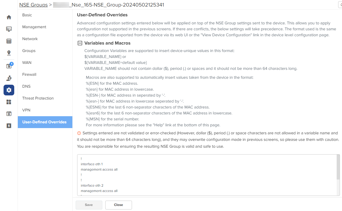
In the text box, enter the configuration that you want to apply to the device.
Click Save.
In the WAN page, you can configure the device’s IPv4 address based on the IP mode.
|
|
Note If PPPoE is used as the WAN connection mode as shown in Figure 64, make sure to configure the PPPoE username and password. Once you have configured the PPPoE user name and password, you can proceed to configure the NSE group by providing the same username and password and then attaching the default NSE group to the device. |
Figure 64 PPPoE as WAN connection mode
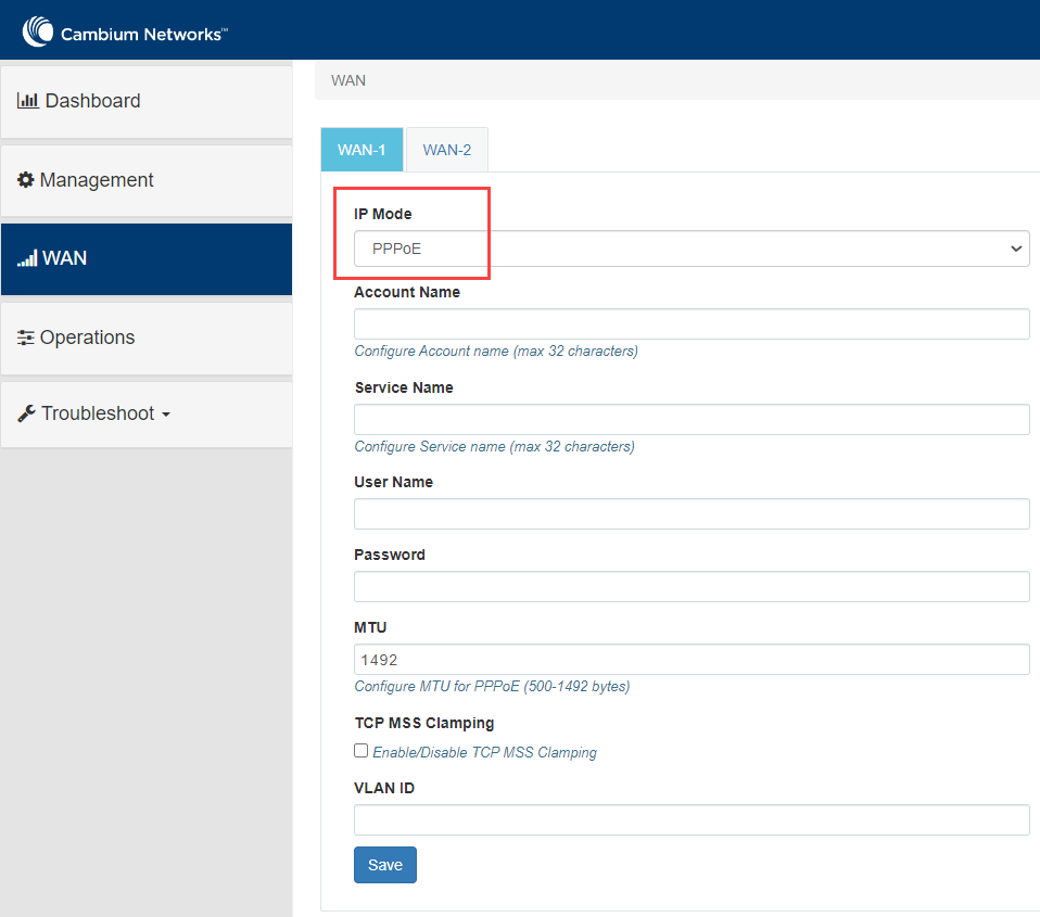
To view and configure the WAN settings, complete the following steps in the device UI:
From the main NSE 3000 dashboard page, click WAN tab from the left panel.
The WAN page appears, as shown in Figure 65.
|
|
Note By default, WAN-1 page appears. You can configure WAN on WAN-1 or WAN-2. |
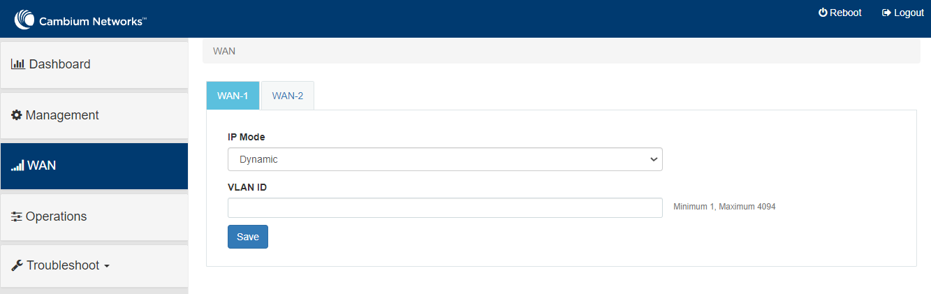
Configure the parameters, as described in Table 15.
Table 15 Parameters on the WAN page
|
Parameter |
Description |
|---|---|
|
IP Mode |
Determines the network that must be configured to use IPv4 addresses. The following options are supported:
By default, the Dynamic mode is selected. |
|
VLAN ID |
The VLAN ID can range from 1 to 4094. The VLAN configuration is optional. When the 802.1Q header is configured, all transmitted frames are expected to include the 802.1Q header with the same VLAN ID. |
|
Following parameters appear only when you select the mode as Static from the IP Mode dropdown list, as shown in Figure 66. |
|
|
IP Address |
The 32-bit binary number that identifies a network element by both network and host. |
|
Subnet Mask |
The subnet mask for the destination IP/network for the route. |
|
Gateway |
The gateway for the destination IP/network for the route. |
|
DNS |
|
|
Primary DNS |
The IPv4 address of primary upstream DNS server. |
|
Secondary DNS |
The IPv4 address of secondary upstream DNS server. |
|
Following parameters appear only when you select the mode parameter as PPPoE from the IP Mode dropdown list, as shown in Figure 67. |
|
|
Account Name |
The name of Access Controller. This parameter allows a maximum of 32 characters. This parameter is optional. |
|
Service Name |
Service name of Access Controller. This parameter allows a maximum of 32 characters. This parameter is optional. |
|
User Name |
A user name for PPPoE authentication. This parameter is mandatory. |
|
Password |
A password for PPPoE authentication. This parameter is optional. |
|
MTU |
MTU for PPPoE interface in bytes. Default: 1492. Range: 500 to 1492 |
|
TCP MSS Clamping |
Indicates whether TCP MSS Clamping is enabled or disabled. By default, this parameter is disabled. |
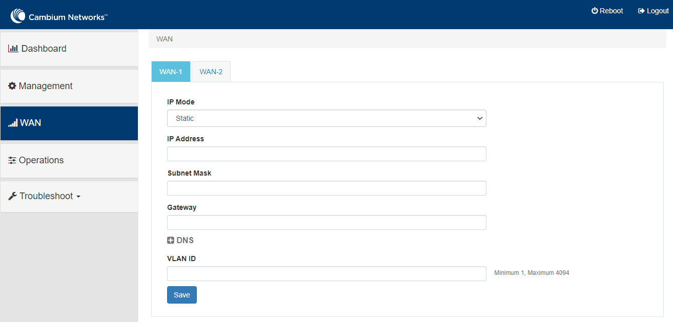
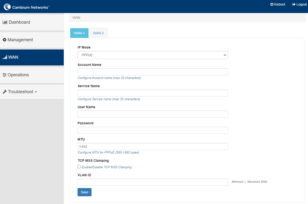
Click Save.
Site-to-site VPN is a secure way of connecting multiple networks across sites. Currently, NSE 3000 supports 100 site-to-site VPN tunnels, However, this site-to-site VPN has some problems specific to device-level configuration, device-level monitoring, and debugging.
As a solution, the Auto VPN feature of NSE offers simplified configuration, monitoring, and debugging of site-to-site tunnels. With this feature, NSE 3000 devices can be networked in either of the following modes: Hub and Spoke, Mesh, or Hybrid. For example, there is one NSE device (two in HA mode) present in one site. With Auto VPN configured, the NSE device connects multiple sites in either one of the modes (Hub and Spoke mode or Mesh' mode).
When Auto VPN is configured using cnMaestro, NSE automates the setting up of site-to-site tunnels for the VPN groups between Cambium NSE devices. Site-to-site tunnels can be deployed either in a Hub and Spoke mode or in full mesh mode.
In the Hub and Spoke mode, 100+ NSE devices can be accommodated in the network, which are connected to a single hub node. There is no need to edit 100 NSE groups to connect all these devices.
The hub can be a non-Cambium device, allowing for greater flexibility in deployment scenarios.
Example: In current deployments of NSE 3000 devices, third-party firewalls are used as hubs and NSE 3000 devices as spokes. If the Hub and Spoke mode is configured, only a single hub (non-Cambium) is used and all the sites are connected to this single hub. In this mode, the spoke devices (NSE) establish secure connections with the hub.
Full mesh deployments require configuring of the networks on each NSE device. When Auto VPN is configured, the devices in the group establish connectivity with the every other member in the group in a full mesh mode.
The Mesh mode is applicable only when the cambium hubs are used.
|
|
Note You CANNOT configure a site-to-site VPN for the NSE 3000 device on which Auto VPN is configured. You must delink the devices from the Auto VPN group to configure the Site-to-Site VPN feature. The device cannot have both site-to-site VPN and auto VPN at the same time. |
Using the cnMaestro UI, you can configure the Auto VPN feature of NSE. The Auto VPN configuration involves the following tasks:
With the flexibility of configuring modes for NSE devices, you can create an Auto VPN group for:
All Cambium hubs: Create an Auto VPN group by disabling the Use non-Cambium Hub option. For details, see Auto VPN group for all Cambium hubs.
A non-Cambium hub: Create an Auto VPN group by enabling the Use non-Cambium Hub option. For details, see Auto VPN group for a non-Cambium hub.
For a traditional Cambium-only setup, you can create auto VPN groups by disabling the Use non-Cambium Hub option. Complete the following steps to configure the Auto VPN group for all Cambium hubs:
From the home page, navigate to Configuration > NSE Profiles.
The NSE Profiles page appears.
On the NSE Profiles page, click the Auto VPNs tab.
The Auto VPNs page appears.
Figure 68 The Auto VPN page
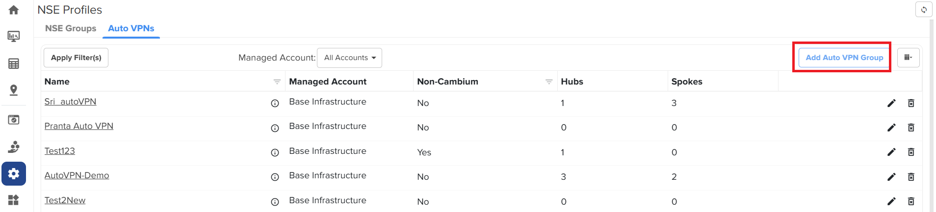
To create a new auto VPN group, click Add Auto VPN Group.
The Add Auto VPN Group window appears.
Figure 69 The Add Auto VPN Group window
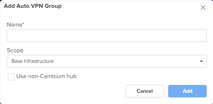
On the Add Auto VPN Group window, provide the values as described:
In the Name field, enter a valid name for the VPN group.
From the Scope dropdown list, select a name of the managed account.
To create the auto VPN goup for all Cambium hubs, ensure that the Use non-Cambium hub checkbox is not selected.
Click Add.
The Auto VPN group for all Cambium hubs is created.
For a hybrid setup where a non-Cambium device serves as the hub, you must enable the Use non-Cambium hub option.
Complete the following steps to configure the Auto VPN group for a non-Cambium hub:
From the home page, navigate to Configuration > NSE Profiles.
The NSE Profiles page appears.
On the NSE Profiles page, click the Auto VPNs tab.
The Auto VPNs page appears.
To create a new auto VPN group, click Add Auto VPN Group.
The Add Auto VPN Group window appears.
On the Add Auto VPN Group window, perform the following steps:
In the Name field, enter a valid name for the group.
Select the required option from the Scope dropdown list.
To create an auto VPN group for a non-Cambium hub, select the Use non-Cambium hub checkbox.
Additional fields are displayed as shown in the figure below.
Figure 70 Additional fields specific to non-Cambium hub settings
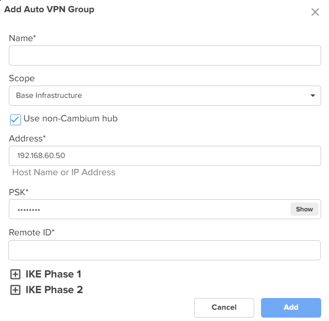
|
|
Note The Address and PSK fields are auto-populated. PSK, a 12-character key, is auto-generated by cnMaestro for Cambium hubs only. This key is used as the local PSK and remote PSK for all the sites in the Auto VPN group. |
In the Remote ID field, enter an appropriate value. This is a mandatory parameter. The remote ID is the local ID of the non-cambium hub device. On creation of a hub or spoke, the local ID (generated sequentially) is assigned as local ID.
Expand the IKE Phase 1 panel.
The default configuration is displayed, as shown in Figure 71.
Figure 71 Default configuration of the IKE Phase 1
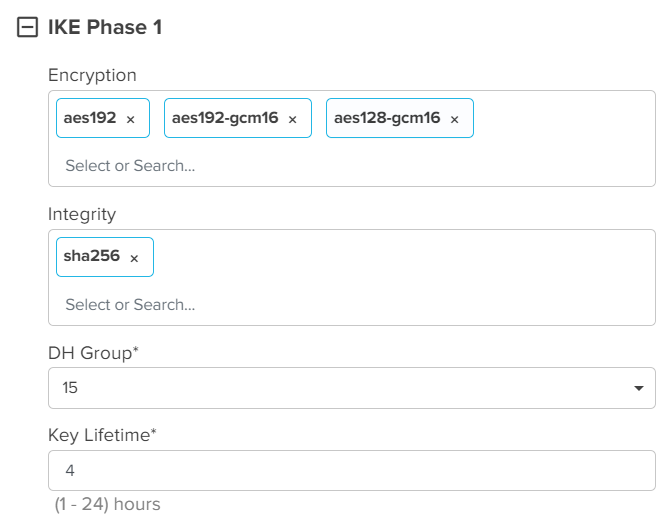
Using the IKE Phase 1 panel, complete the following steps:
In the Encryption field, select the required encryption method. By default, aes192, aes192-gcm16, aes128-gcm16 are selected.
In the Integrity field, select the required integrity method. By default, sha256 is selected.
In the DH Group field, select the required DH group option. Default value: 15.
In the Key Lifetime field, enter a value. Default value: 4.
Similarly, expand the IKE Phase 2 panel and set the configuration.
The default configuration is shown in Figure 72.
Figure 72 Default configuration of the IKE Phase 2
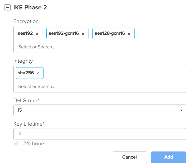
Click Add.
The Auto VPN group is created for a non-Cambium hub.
You must add hubs and spokes as part of the Auto VPN configuration. A site has to be linked at the time of creating a hub or a spoke. You must select a site from the list of sites and this site must have met the following criteria:
The site should have an NSE device.
An NSE group should be mapped to the NSE device.
The site should not be part of any other Auto VPN group.
|
|
Note
|
This topic covers the following sections:
You can add a single or multiple hubs and spokes for a Cambium-hub Auto VPN group.
Complete the following steps to add a hub:
On the NSE Profiles page, click the Auto VPNs tab.
The Auto VPNs page appears with a list of auto VPN groups created.
Figure 73 The Auto VPNs page
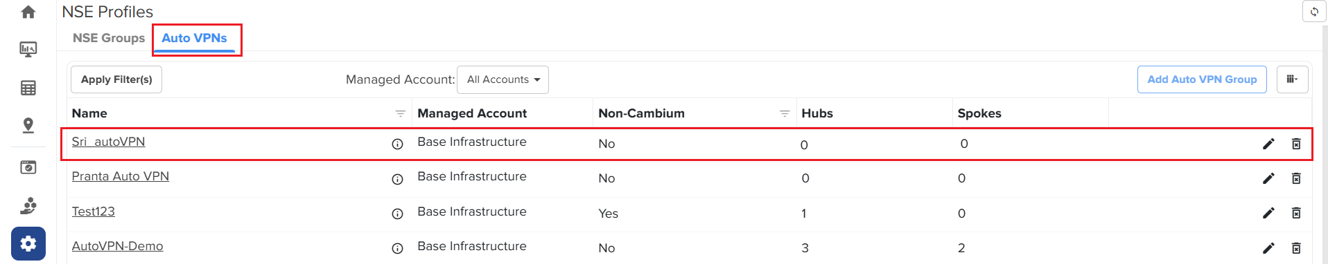
If the value of Non-Cambium field on the Auto VPN page is No, then it is a Cambium-hub Auto VPN group. Otherwise, it is a non-Cambium hub Auto VPN group (if the value of Non-Cambium is Yes).
Click on the required Cambium-hub Auto VPN group name.
The Configuration page appears for the selected auto VPN group.
Figure 74 The Configuration page
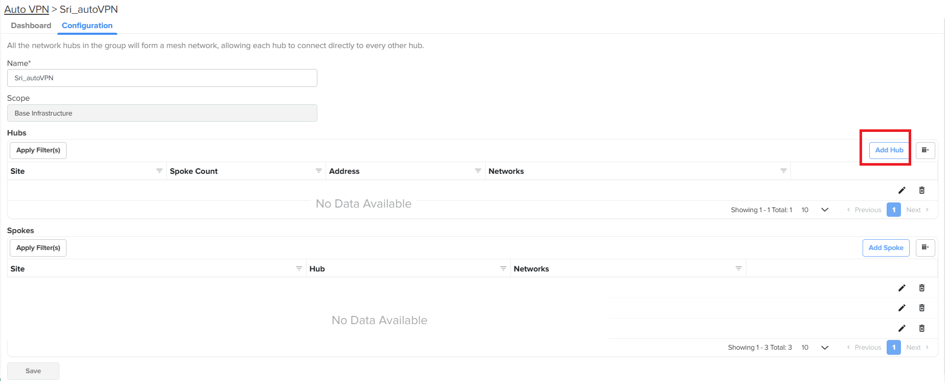
Click Add Hub.
The Add Hub window appears.
Figure 75 The Add Hub window
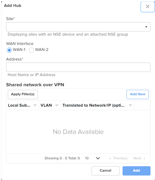
To add a hub, provide the values as described:
From the Site dropdown list, select a site name. This is a mandatory field.
The Site dropdown list displays sites that have an NSE device and an attached NSE group.
In the WAN Interface field, select the required WAN option.
In the Address field, enter the host name or WAN IP address of the NSE 3000 device. This is a mandatory field.
This field auto-populates the value with WAN 1 or WAN 2 IPs if the static IPs are configured.
In the Shared network over VPN section, Click Add New to add VLAN IDs of required networks.
The Add New Local Subnet window appears. Using this window, you can add networks that the hub will advertise. You can add multiple networks.
Figure 76 The Add New Local Subnet window
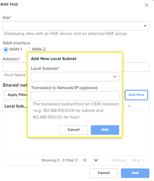
In the Add New Local Subnet window, enter a valid address in the Local Subnets field. The Translated to Network/IP (optional) field is optional. If the Local subnets have a VPN translation, then provide a VPN network address in the Translated to Network/IP (optional) field or it can be left blank (empty).
Click Add on the Add New Local Subnet window.
The shared network details are added to the Add Hub window.
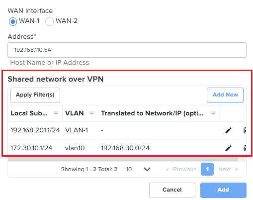
The NSE 3000 device communicates over the specified VLAN.
Click Add on the Add Hub window.
A hub is added to the Hubs section on the Configuration page.
Figure 77 The Hubs section
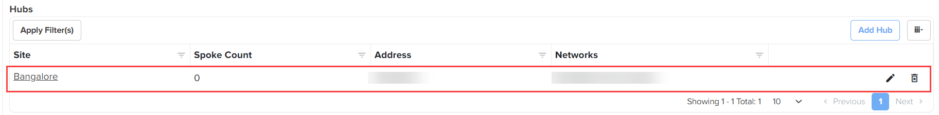
Adding a spoke
Complete the following steps to add a spoke:
On the NSE Profiles page, click the Auto VPN tab.
The Auto VPN page appears with a list of auto VPN group created.
Click on the required auto VPN group name.
The Configuration page appears for the selected auto VPN group.
Figure 78 The Configuration page - Add Spoke
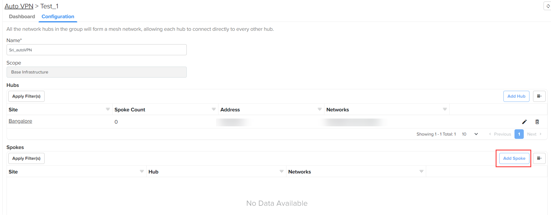
Click Add Spoke.
The Add Spoke window appears.
Figure 79 The Add Spoke window
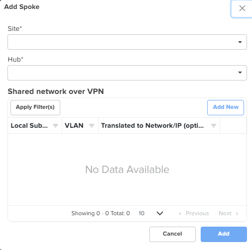
Complete the following steps to add a spoke:
Select a site from the Site dropdown list. This is a mandatory field.
Select a hub from the Hub dropdown list. This is a mandatory field. You must select a hub to connect from the list of hubs, which are already created in the Auto VPN group.
In the Shared network over VPN section, Click Add New. The Add New Local Subnet window appears.
Using this window, you can add networks that are local to the spoke. You can add multiple networks. If there are multiple hubs, these networks will be advertised by the hub they are connected to.
In the Add New Local Subnet window, enter a valid address in the Local Subnets field. The Translated to Network/IP (optional) field is optional. If the Local subnets have a VPN translation, then provide a VPN network address in the Translated to Network/IP (optional) field or it can be left blank (empty).
Click Add on the Add New Local Subnet window. The shared network details are added to the Add Spoke window. The NSE 3000 device communicates over the specified VLAN.
Click Add on the Add Spoke window.
A spoke is added to the Spokes section.
Figure 80 The Spokes section
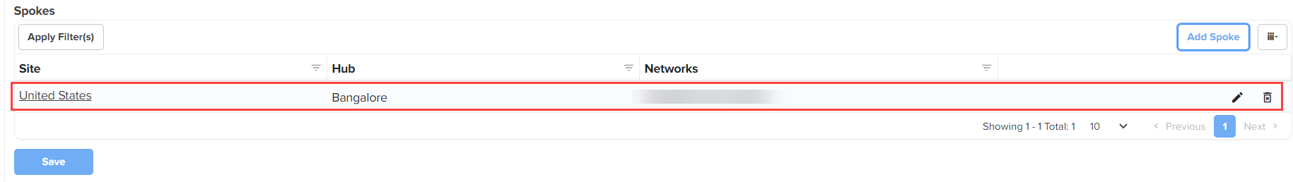
Click Save on the Configuration page.
The figure below is an example of the Configuration page for a Cambium-hub Auto VPN group (after adding a hub and a spoke). You can add multiple hubs and spokes for a Cambium-hub Auto VPN group.
Figure 81 The Configuration page for a Cambium-hub Auto VPN group
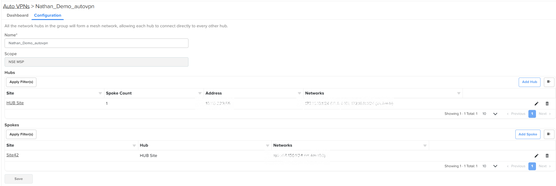
Click Save on the Configuration page to apply the changes.
To view the dashboard page for the configured Auto VPN group, click on the Dashboard tab (located before the Configuration tab).
You can view the status of connection and tunnel type used by the NSE 3000 device for communication.
Figure 82 The Dashboard page of an Auto VPN group
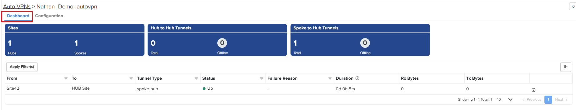
On the Dashboard page, click on the  icon (next to Tx Range) to view the network details.
Figure 83 The Networks page
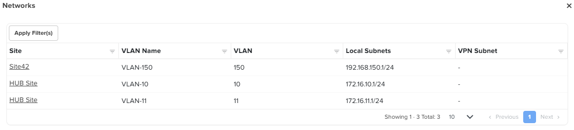
You can add a single or multiple spokes for a non-Cambium hub Auto VPN group. You cannot add a hub but you can update or modify its configuration for a non-Cambium hub Auto VPN group.
Complete the following steps to add a spoke:
On the NSE Profiles > Auto VPNs page, select a non-Cambium hub Auto VPN group from the available list.
If the value of Non-Cambium field on the Auto VPNs page is Yes, then it is a non-Cambium hub Auto VPN group.
Figure 84 The Auto VPNs page - Non-Cambium hub
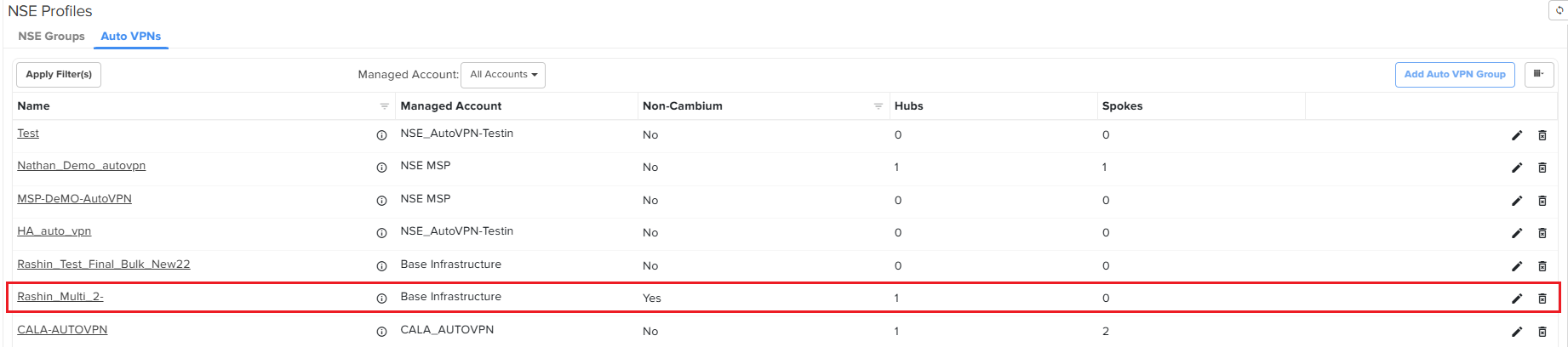
Click on the required non-Cambium hub Auto VPN group name.
The Configuration page appears for the selected auto VPN group.
Figure 85 The Configuration page - Non-Cambium hub
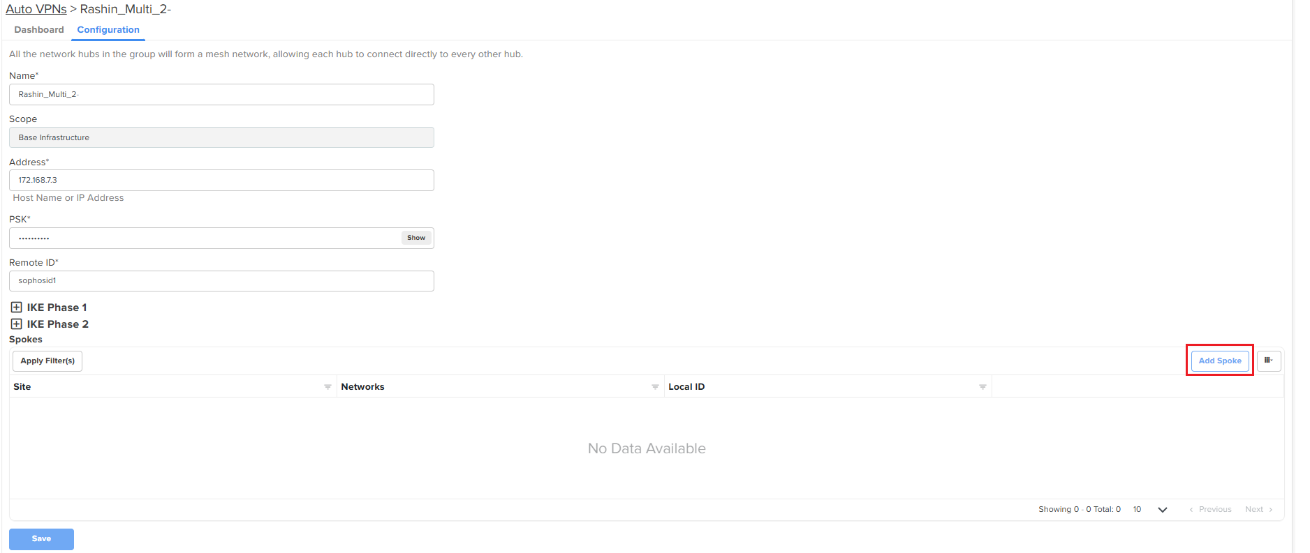
The following parameters are already set at the time of creating a non-Cambium hub Auto VPN group:
Name
Scope
Address
PSK
Remote ID
IKE Phase 1 and IKE Phase 2
You can update or modify the hub-specific parameters except for Scope (disabled). For more information about these parameters, check Auto VPN group for a non-Cambium hub.
To add a spoke for a non-Cambium hub Auto VPN group, click Add Spoke on the Configuration page.
The Add Spoke window appears.
Figure 86 The Add Spoke window - Non-Cambium hub
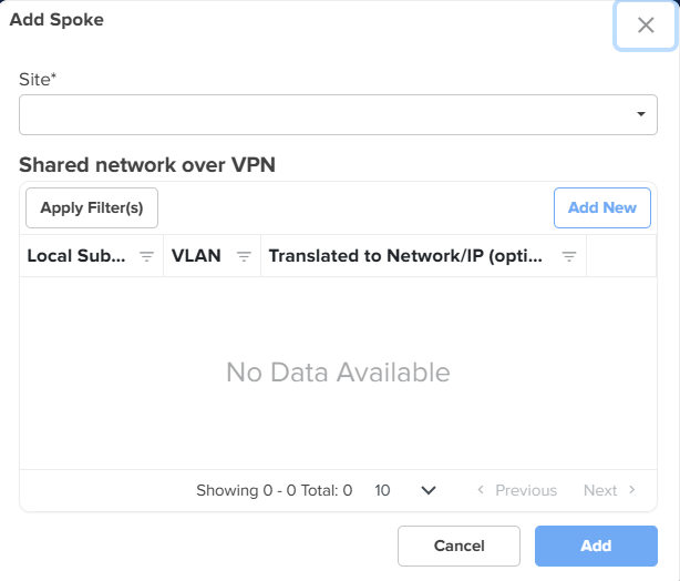
Complete the following steps to add a spoke:
Select a site from the Site dropdown list. This is a mandatory field.
In the Shared network over VPN section, Click Add New. The Add New Local Subnet window appears.
Using this window, you can add networks that are local to the spoke. You can add multiple networks. These networks will be advertised by the hub they are connected to.
|
|
Note NSE 3000 supports VPN translation. For more information, check the note described here. |
In the Add New Local Subnet window, enter a valid address in the Local Subnets field. The Translated to Network/IP (optional) field is optional. If the Local subnets have a VPN translation, then provide a VPN network address in the Translated to Network/IP (optional) field or it can be left blank (empty).
Click Add on the Add New Local Subnet window. The shared network details are added to the Add Spoke window. The NSE 3000 device communicates over the specified VLAN.
Click Add on the Add Spoke window.
A spoke is added to the Spokes section.
Click Save on the Configuration page to apply the changes.
To view the dashboard page for the configured Auto VPN group, click on the Dashboard tab (located before the Configuration tab).
On the Dashboard page, you can use the icon (next to Tx Range) to view the network details.
Currently, a subscription is required to onboard and manage NSE 3000 using cnMaestro (both Essentials and X). This paid subscription license mode (with all features available) is referred to as Security Plus.
However, Cambium Networks also offers a flexibility to onboard and manage NSE 3000 devices using cnMaestro without a subscription. This subscription-free license mode is referred to as Security. The Security mode allows you to onboard and operate an NSE 3000 device with limited features.
|
|
Note The Security Plus license mode is available for both cnMaestro Essentials and X. But the Security mode is available only for cnMaestro Essentials. |
The table below lists some of the features available in the Security Plus license mode and the Security mode.
Table 16 List of feature sets available for NSE in different license modes
|
Feature sets available in the Security Plus license mode (Paid subscription) |
Feature sets available in the Security mode (Subscription-free) |
|---|---|
|
|
With the introduction of the new feature sets, the following three different account states are observed for NSE in cnMaestro:
cnMaestro Essentials with Security: Free subscriptions (1000 free slots) are granted for NSE devices.
cnMaestro Essentials with Security Plus: The user needs to activate Tier 30 licenses for all NSE devices.
cnMaestro X with Security Plus: The user needs to activate Tier 30 licenses for all NSE devices.
How does the Security Plus license mode work?
By default, the Security Plus license mode is enabled for NSE and all the features are available for existing and new user accounts. In this default license state, all the security features, such as Geo-IP firewall, DNS content filtering, high availability, LAN vulnerability assessment, device identification, device fingerprinting, and cnMaestro reports are enabled.
Using cnMaestro Essentials, you can disable the Security Plus mode and switch to the Security mode (subscription-free). You can also switch back (enable) to the Security Plus mode. For details, refer to Disabling the Security Plus mode and Enabling the Security Plus mode.
How does the Security (subscription-free) mode work?
The subscription model for NSE devices remains unchanged but cnMaestro grants a free subscription if the user chooses to use only the Security mode in cnMaestro Essentials.
To switch to the Security mode, an account-level setting is required in the cnMaestro UI. When you select between Security and Security Plus modes, cnMaestro verifies before changing the mode and throws an error if any of the criteria fails.
On changing to the Security mode, cnMaestro activates 1000 (configurable) Tier 30 free slots with a rotating validity period (after which cnMaestro resets to a future date before a slot reaches its expiry). These free slots cannot be transferred to X unlike the regular Tier 30 slots.
When the Security mode is enabled, cnMaestro automatically disables all features that are supported in the Security Plus mode. For information on how to enable the Security mode, refer to Disabling the Security Plus mode.
|
|
Note If an account running in the Security mode (earlier) is upgraded to X, then cnMaestro automatically toggles it to the Security Plus mode. |
How to switch back to Security Plus mode?
To switch back to (enable) the Security Plus mode, an account-level setting is required in the cnMaestro UI. However, the users should have activated sufficient number of Tier 30 licenses to meet their NSE device count (as a prerequisite task). On changing to the Security Plus mode, cnMaestro deactivates the grant (free subscription) and all features are available in this mode (by default). For information on how to switch back to the Security Plus mode in cnMaestro, refer to Enabling the Security Plus mode.
|
|
Note Fresh accounts are initialized with Essentials and Security Plus. That is, the user needs to activate Tier 30 licenses to manage an NSE device. |
How do license modes work during a manual or automatic downgrade from X?
Automatic downgrade happens when all activated subscriptions (licenses) expire for the X account.
When automatically downgraded from X, the Security Plus mode is continued in Essentials and any devices without valid licenses are marked as expired. If you want to use the Security license mode, you must disable the Security Plus mode using the Administration > Settings > General page in cnMaestro UI. For details, refer to Disabling the Security Plus mode.
|
|
Note Switching to Security mode will automatically reactivate the expired devices. |
A manual downgrade from X is possible under the following three conditions for NSE:
If all required Tier 30 subscriptions are available, then the Security Plus mode can be continued in Essentials.
If partial Tier 30 subscriptions are available, then cnMaestro continues in the Security Plus mode and devices without valid Tier 30 licenses are marked as expired.
If no Tier 30 Subscriptions are available, then cnMaestro follows the automatic downgrade path.
When you disable the Security Plus mode for NSE using cnMaestro Essentials, the Security mode (subscription-free) is enabled. Complete the following steps to disable the Security Plus mode:
Log in to cnMaestro Essentials using appropriate username and password.
From the home page, navigate to Administration > Settings. The Settings page appears with the following tabs: General, Notifications, and Software Images. By default, the General tab is selected.
The General page displays Time zone, Account view, Zero Touch Onboarding, and NSE Security Plus settings (default state).
On the General page, go to the NSE Security Plus section.
Figure 87 The NSE Security Plus section
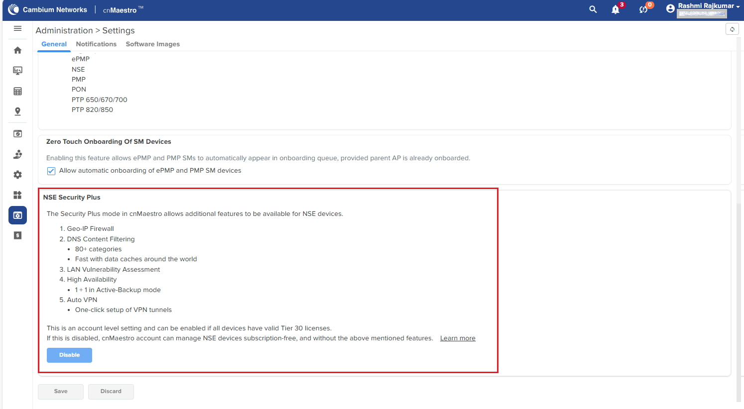
By default, the Security Plus mode is enabled for the NSE devices. In the NSE Security Plus section (as shown in Figure 1), you can view the details of features enabled.
To disable the Security Plus mode, click the Disable button.
The process begins, indicating the subscription provisioning and device sync as shown in Figure 2.
Figure 88 Process of disabling the Security Plus mode
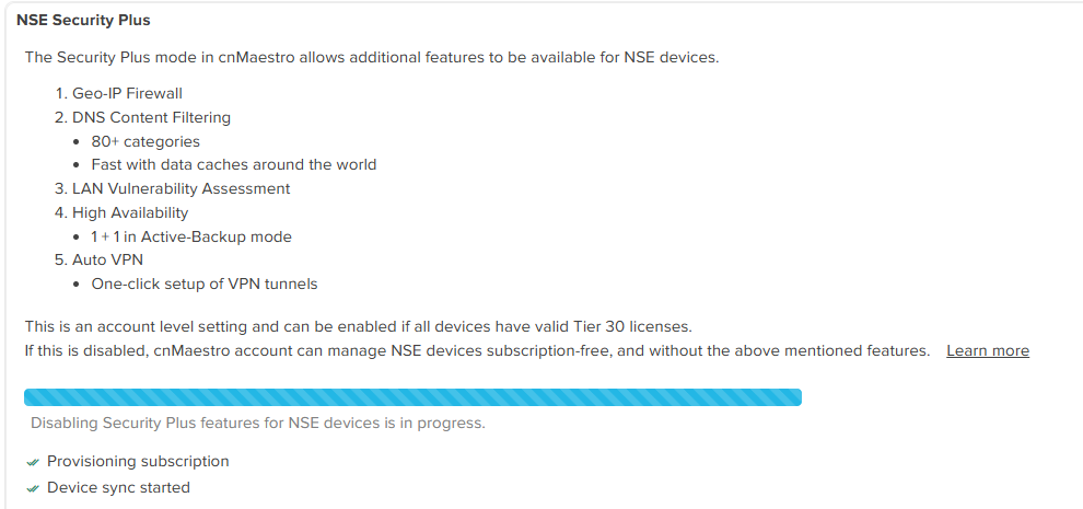
The Security license mode is enabled now. You can proceed with configuration of the related features on the NSE Groups page. For example, WAN and LAN services. Check Table 16 for the list of feature sets available in the Security mode (subscription-free).
When the Security mode is enabled, the unsupported features are disabled in the cnMaestro UI. Feature-level messages are displayed on the UI as part of the configuration for the NSE device.
Based on the account level mode selection, the cnMaestro UI turns off (disable) and turns on (enable) the related features. For example, if you select the Basic tab on the NSE Groups page, a feature level message is visible, indicating that the high availability (HA) configuration is available only with the Security Plus mode. In addition, the HA configuration checkbox is disabled and provides an option (link) to enable the Security Plus mode (as shown in Figure 3).
Figure 89 Example of a feature-level message
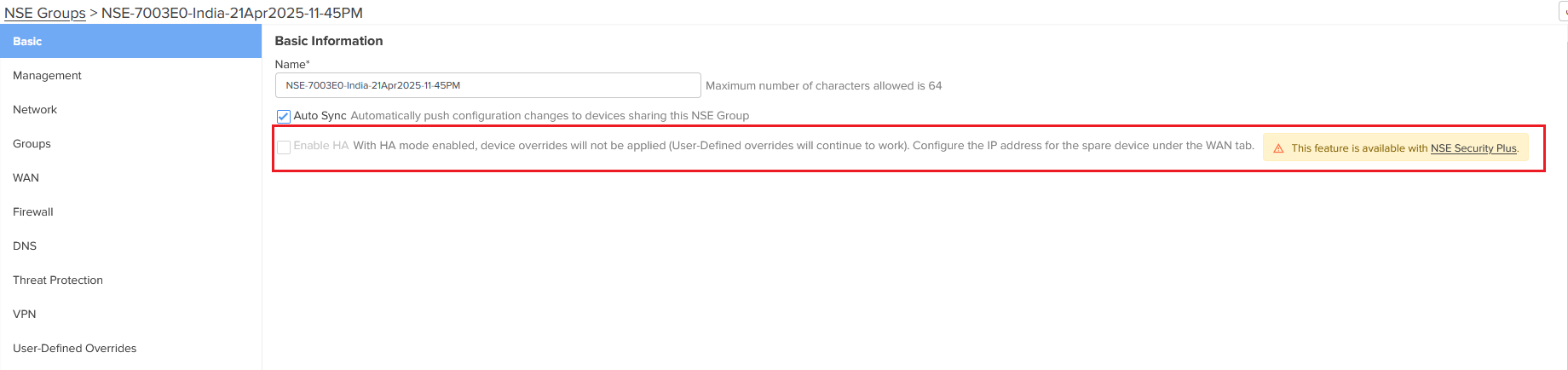
Similarly, you can find such feature-level messages for specific configurations on Firewall and DNS pages for the Security mode. In addition, Vulnerabilities is not available at all levels, and Auto VPN, GEO IP Firewall, and DNS Content Filtering are also unavailable.
Configure the required features available in the Security mode.
cnMaestro grants 1000 free slots, which you can use to onboard and manage the NSE devices. To view the summary of grant, check the Manage Subscriptions page. Figure 4 is an example of a grant summary, showing that one slot is used, and 1099 free slots are available for NSE devices. These free slots can be used to onboard and manage the NSE devices in cnMaestro.
Figure 90 Viewing the grant summary on the Manage Subscriptions page
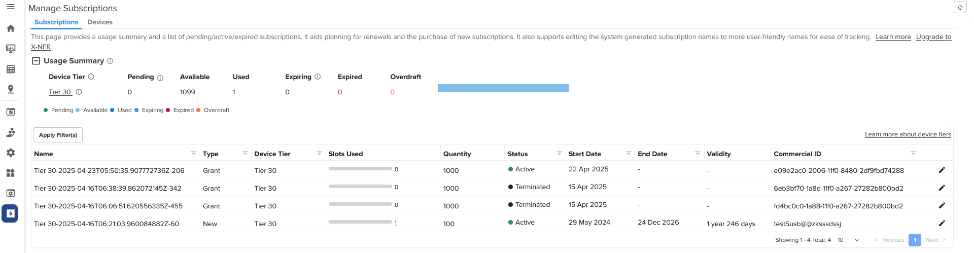
You have an option to enable or switch back to the Security Plus mode in cnMaestro. With this action, the Security mode is disabled and all features (available in the Security Plus mode) are enabled automatically.
To switch back to or enable the Security Plus mode, complete the following steps:
From the home page of cnMaestro Essentials, navigate to Administration > Settings. By default, the General tab is selected.
On the General page, go to the NSE Security Plus section.
Figure 91 The NSE Security Plus section with the Enable button
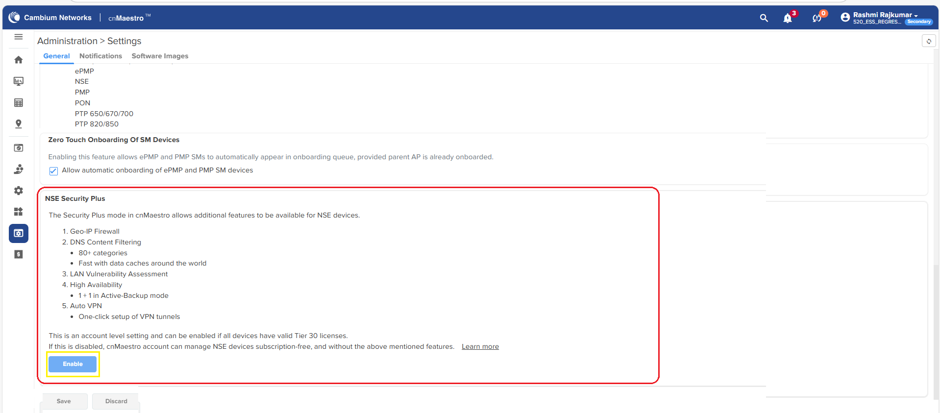
To enable the Security Plus mode, click the Enable button in the NSE Security Plus section.
The process of enabling the Security Plus mode begins, as shown in Figure 6.
Figure 92 Enabling the Security Plus mode - cnMaestro Essentials
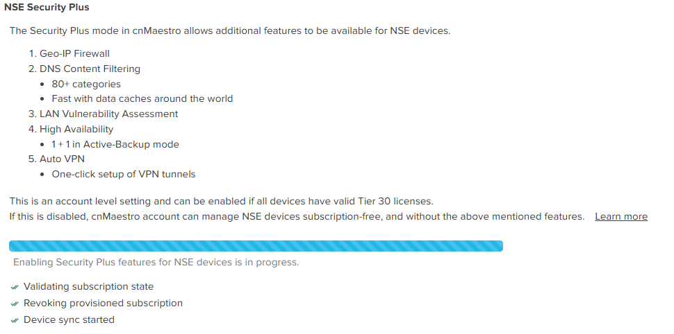
Click Save to apply the change when the process is complete.
You have now enabled the Security Plus mode for the NSE devices. With this action, all features, such as high availability, firewall settings, vulnerabilities, and Auto VPN, are enabled in the cnMaestro UI.